Bracket-active grille and actuator

a technology of active grilles and actuators, which is applied in the direction of machine supports, transportation and packaging, and other domestic objects, can solve the problems of changing the operation of components, the engine is the least fuel efficient, and the components designed to provide optimal cooling for the new vehicle may operate differently, so as to reduce the design and tooling. , the effect of simplifying and reducing labor tim

Active Publication Date: 2014-09-09
MAGNA INTERNATIONAL INC
View PDF22 Cites 12 Cited by
  • Summary
  • Abstract
  • Description
  • Claims
  • Application Information

AI Technical Summary

Benefits of technology

[0009]The bracket also includes a plurality of alignment features integrally formed as part of the bracket. The alignment features support and properly position the actuator within the cavity. The design of the present invention reduces and simplifies design and tooling, and also has minimal components and fasteners, which also simplifies and reduces labor time.

Problems solved by technology

When the engine is substantially the same temperature as the surrounding environment and is turned on, the engine is the least fuel efficient (especially during start-up and the temperature of the surrounding environment is cold).
Furthermore, components designed to provide optimal cooling when the vehicle is new may operate differently after the vehicle has accumulated significant mileage.
This may occur due to various weather conditions, changes in the way the vehicle is operated in response to different drivers, or wear and tear on the vehicle components and other components.
All of these factors may affect or change the operation of the components over time as the vehicle accumulates mileage.
Also, with many current cooling systems, the airflow generated from the forward motion of a vehicle is not efficiently used to cool the various components of the vehicle.
Rather, many of the components of a vehicle cause poor airflow which leads to aerodynamic inefficiencies.

Method used


Image

  • Bracket-active grille and actuator
  • Bracket-active grille and actuator
  • Bracket-active grille and actuator

Examples


first embodiment

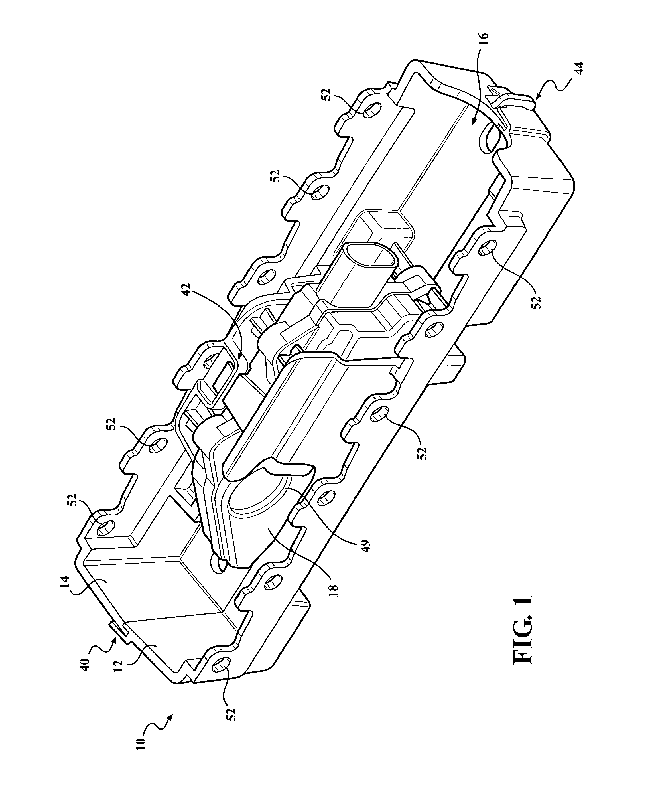
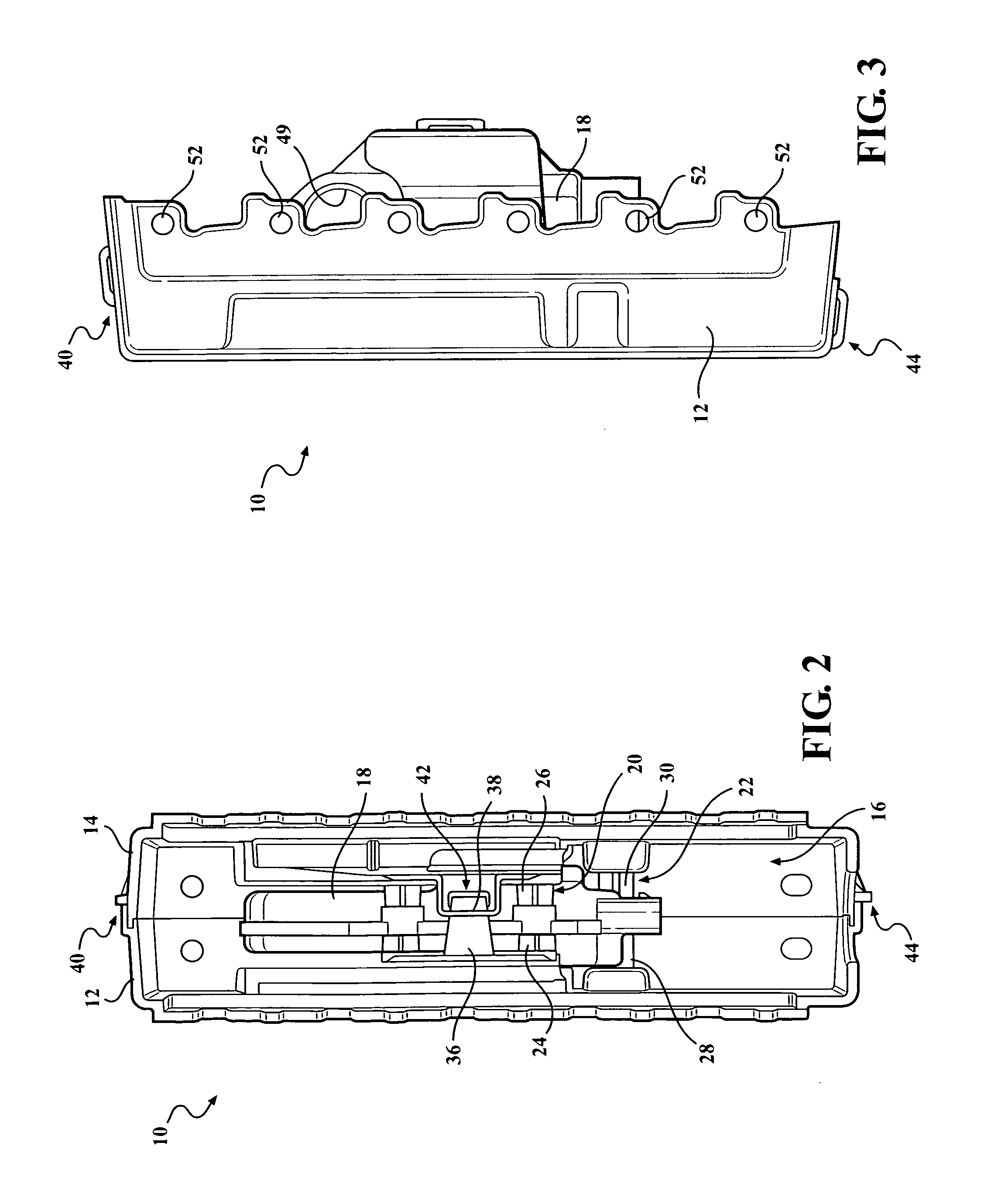
[0040]a bracket according to the present invention is shown in FIGS. 1-8 generally at 10. The bracket 10 includes a first piece 12 and a second piece 14, which when connected together form a cavity, shown generally at 16, for receiving an actuator 18. In this embodiment, each piece 12,14 represents half of the bracket 10, but it is within the scope of the invention that the bracket 10 may be made of a single piece, or more than two pieces.

[0041]The bracket 10 also includes a plurality of alignment features, some of which are a first plurality of alignment features, shown generally at 20, and some of which are a second plurality of alignment features, shown generally at 22. Each of the first plurality of alignment features 20 is made up of a first projection 24 formed as part of the first piece 12 of the bracket 10, and a second projection 26 formed as part of the second piece 14 of the bracket 10. In this embodiment, the first projection 24 has an X-shaped cross section which is in ...

second embodiment

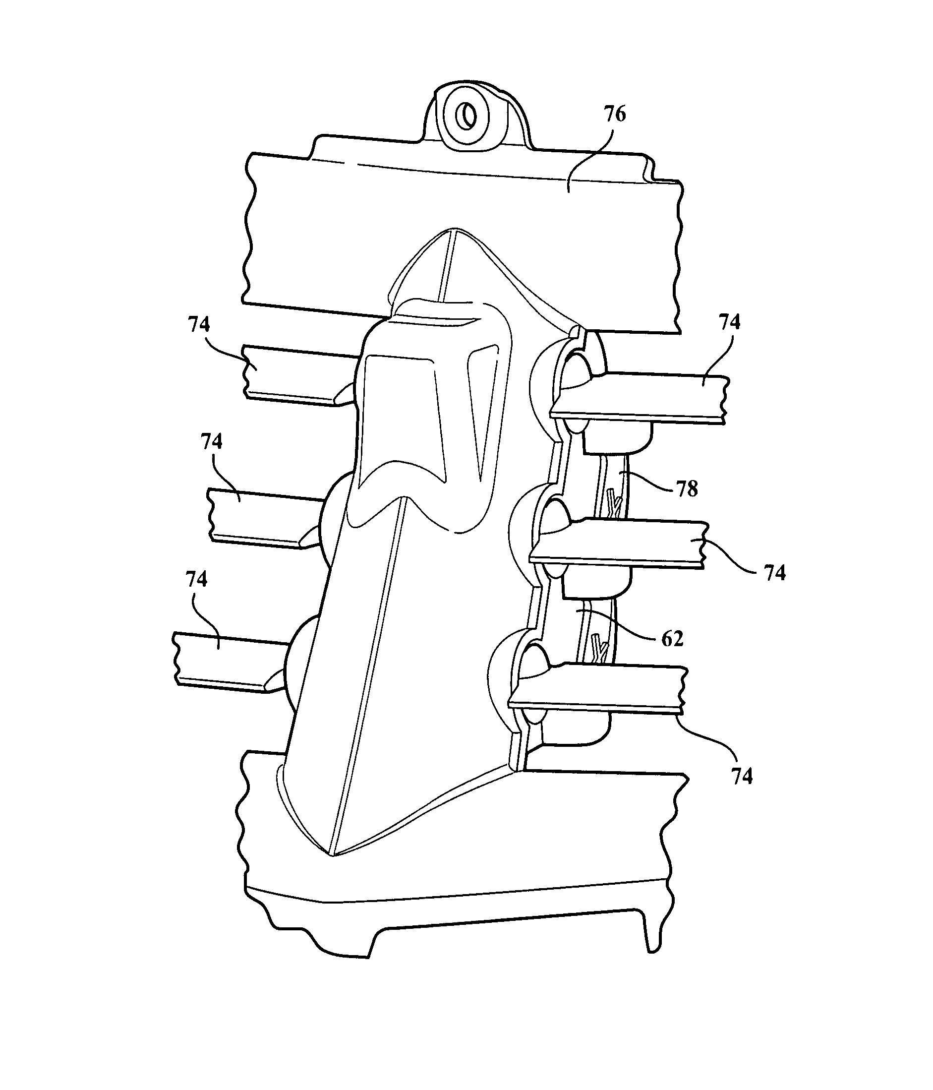
[0054]the bracket 60 is not limited to the use of the first locator projection 68 used in combination with the second locator projection 72, or the third locator projection 138 in combination with the fourth locator projection 140. As an alternate embodiment, the fourth projection 140 formed as part of the second piece 64 may extend through one of the apertures 32 and contact a boss 150 formed as part of the first piece 62, shown in FIG. 18. In yet another alternative embodiment, the third locator projection 138 may extend through an aperture 32 in the actuator 32 and contact a boss 152 formed as part of the second piece 64.

[0055]There is also a locating feature 148 formed as part of the first piece 62. The locating feature 148 extends into one of the apertures 32 formed as part of the actuator 18, and contacts an inner surface of the second piece 64, to further locate the actuator 18 in the cavity 66 of the bracket 60.

[0056]The second embodiment of the bracket 60 also includes the ...


PUM


Abstract

A modular a bracket which forms a cavity such that the bracket surrounds and supports an actuator. In one embodiment, the bracket is made of multiple pieces and also connects together without the use of fasteners. The pieces are connected together through the use of several attachment features, with a portion of each of the attachment features integrally formed as part of each half. The bracket also includes a plurality of alignment features integrally formed as part of the bracket. The alignment features support and properly position the actuator within the cavity. The design of the bracket reduces and simplifies design and tooling, and also has minimal components and fasteners, which also simplifies and reduces labor time.

Description

CROSS-REFERENCE TO RELATED APPLICATIONS[0001]This application claims priority to U.S. Provisional Application No. 61 / 456,984 filed on Nov. 16, 2010. The disclosure of the above application is incorporated herein by reference.FIELD OF THE INVENTION[0002]The present invention relates to a bracket used for supporting an actuator and a plurality of louvers in a grille having active ducting.BACKGROUND OF THE INVENTION[0003]Various attempts have been made to optimize the cooling of various automobile parts. Some of the various devices developed have been designed to control the air flow throughout the engine compartment of the automobile such that the desired amount of heat is transferred away from the engine, transmission, and other components which generate heat in order to maintain an optimal operating temperature.[0004]However, it is also desirable to bring the engine up to the normal operating temperature as soon as possible after engine start-up. When the engine is substantially the...

Claims


Application Information

Patent Timeline
Patent Type & Authority Patents(United States)
IPC IPC(8): F16M11/00
CPCF24F13/20B60K11/085Y02T10/88
Inventor CRANE, MICHAEL W.COBB, THOMAS EDWINPOVINELLI, ANTHONY J.KOWALSKI, JAMES J.RODDY, STEVEN R.
Owner MAGNA INTERNATIONAL INC
Why Eureka
Try Eureka