Printing apparatus

a printing apparatus and printing technology, applied in printing, other printing apparatus, etc., can solve the problems of difficult rapid judgment of the discharge state, large printing apparatus, and inability to quickly judge the discharge sta

Active Publication Date: 2014-09-30
CANON KK
View PDF24 Cites 4 Cited by
  • Summary
  • Abstract
  • Description
  • Claims
  • Application Information

AI Technical Summary

Benefits of technology

[0016]For example, a printing apparatus according to this invention is capable of executing judgment of the discharge state of each nozzle or judgment of discharge failure occurrence accurately at an appropriate timing while suppressing an apparatus from becoming bulky and expensive.
[0019]The invention is particularly advantageous since it is possible to execute judgment of the discharge state of each nozzle or judgment of discharge failure occurrence accurately at an appropriate timing while suppressing an apparatus from becoming bulky and expensive.

Problems solved by technology

In this printhead, an ink discharge failure may occur in some or all of the nozzles of the printhead due to nozzle clogging caused by foreign substances or high viscosity ink, bubbles trapped in an ink supply channel or a nozzle, a change in wettability on a nozzle surface, or the like.
In the discharge state judgment method disclosed in Japanese Patent Laid-Open No. 6-079956, however, it is very difficult to quickly judge the discharge state because a nozzle with a discharge failure is detected based on the reading result of a check pattern printed on a paper sheet, assuming that the check pattern is printed prior to the judgment.
In addition, a reading apparatus needs to be provided, and accordingly, the printing apparatus becomes bulky and expensive.
In the arrangements disclosed in Japanese Patent Laid-Open Nos. 3-234636 and 3-194967 as well, the apparatus has difficulty in downsizing and cost reduction.
It is also difficult to quickly detect a nozzle having discharge failure.
However, the arrangements are still insufficient for accurately judging the discharge state.
Especially, in Japanese Patent Laid-Open No. 2-28935, it is impossible to accurately specify a nozzle with discharge failure.

Method used


Image

  • Printing apparatus
  • Printing apparatus
  • Printing apparatus

Examples


first embodiment

[0073][First Embodiment]

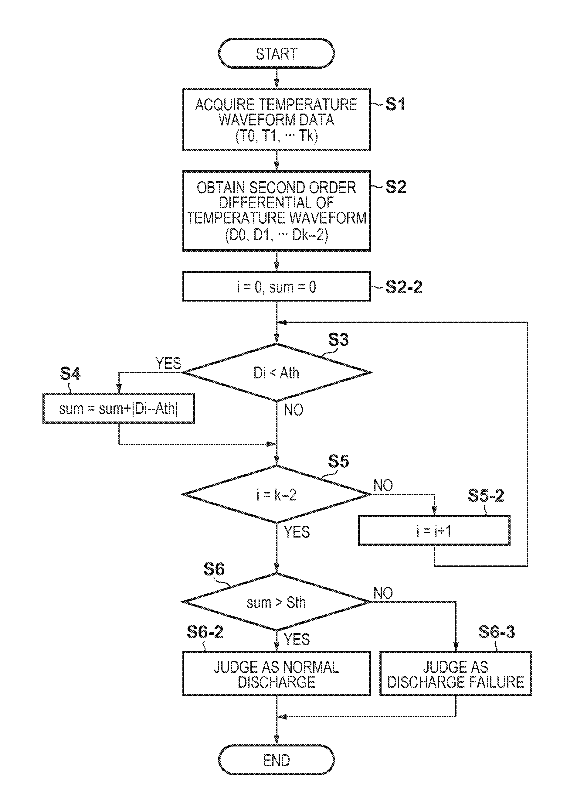
[0074]FIG. 7 is a graph showing the relationship between an addition threshold and the second derivatives (d2T / dt2) of the temperature detected by a temperature sensor 105 in respect with a time at the time of normal discharge and at the time of a discharge failure occurrence according to the first method. In FIG. 7, T is a temperature, and t is a time.

[0075]In the normal discharge, the negative peak that appears in the second derivative has a smaller value, and the positive peak has a larger value than in the second derivative at the time of the discharge failure. Hence, if the second derivative is added without using the addition threshold, the negative peak and the positive peak cancel each other, and the difference from that at the time of the discharge failure is not so large. In addition, the waveform of the temperature detected by the temperature sensor 105 has a variation caused by the difference in the head or nozzle. In this method, the addition thr...

second embodiment

[0108][Second Embodiment]

[0109]FIG. 13 is a graph showing an intermediate time threshold ITth. In this embodiment, when an extraction intermediate time IT at which the cumulative value exceeds a predetermined intermediate cumulative threshold is smaller than a predetermined intermediate time threshold, the discharge state is judged as normal discharge. If the extraction intermediate time IT is larger, the discharge state is judged as discharge failure.

[0110]FIG. 14 is a flowchart showing a discharge state judgment procedure according to the second embodiment.

[0111]As can be seen by comparing FIG. 14 with FIG. 12, the procedure of this embodiment is different from that shown in FIG. 12 in how to provide the threshold for the cumulative value. That is, in FIG. 12 according to the first embodiment, the intermediate cumulative value isum at the intermediate detection time IDT is used as the judgment criterion in step S5-2. In FIG. 14 according to this embodiment, however, the comparison...

third embodiment

[0116][Third Embodiment]

[0117]FIG. 15 is a graph showing a first intermediate cumulative value isum1 and a second intermediate cumulative value isum2. In this embodiment, two predetermined intermediate cumulative values are prepared, and the difference between times at which the cumulative value exceeds the intermediate cumulative values is defined as an amplification time AT. The amplification time is compared with a predetermined amplification time threshold ATth. Unless AT1 at time t=F1, and exceeds the second intermediate cumulative value isum2 at time t=F2. Hence, in this case, the amplification time AT is AT=F2−F1. In normal discharge, when the cumulative value (dT / dt) is lower than a normal cumulative value, the cumulative value exceeds the first intermediate cumulative value isum1 at time t=S1, and exceeds the second intermediate cumulative value isum2 at time t=S2. Hence, in this case, the amplification time is AT=S2-S1.

[0118]FIG. 16 is a flowchart showing a discharge state...


PUM


Abstract

This invention has been made to judge the discharge state of each nozzle accurately at an appropriate timing. For this purpose, an apparatus using a printhead including a heater and a temperature sensor has the following arrangement. A temporal change in a detected temperature is monitored upon driving the printhead. During the temperature drop, temperatures are extracted at plural points of a time interval including a timing at which a feature point of the temporal change in the detected temperature in normal discharge appears. The second derivative of the temperature is calculated and added to obtain a total sum and intermediate sum. The total sum is compared with predetermined first and second thresholds to judge whether to normally discharge ink. If normal discharge or discharge failure is uncertain, the intermediate sum is compared with a third threshold for final judgment.

Description

BACKGROUND OF THE INVENTION[0001]1. Field of the Invention[0002]The present invention relates to a printing apparatus and, more particularly, to a printing apparatus that uses a printhead including a heating element (heater) to discharge ink.[0003]2. Description of the Related Art[0004]Some of inkjet printing methods of discharging ink droplets from nozzles and adhering them to a printing medium such as a paper sheet or a plastic film use a printhead including a heater that generates heat energy to discharge ink. For a printhead according to this method, for example, electrothermal transducers, a driving circuit thereof, and the like, can be formed using the same process as a semiconductor manufacturing process. Hence, the printhead has the advantages of facilitating high-density nozzle integration and achieving high-resolution printing.[0005]In this printhead, an ink discharge failure may occur in some or all of the nozzles of the printhead due to nozzle clogging caused by foreign ...

Claims


Application Information

Patent Timeline
Patent Type & Authority Patents(United States)
IPC IPC(8): B41J29/393
CPCB41J2/0451B41J2/0454B41J2/04563B41J2/0458B41J2/14129B41J2/14153B41J2/16579B41J2002/14354
Inventor IKE, TAKESHI
Owner CANON KK
Why Eureka
Try Eureka