Reduced rating output rectifier snubber for plasma cutting power supply

Inactive Publication Date: 2007-02-08
HYPERTHERM INC +1
View PDF3 Cites 13 Cited by
  • Summary
  • Abstract
  • Description
  • Claims
  • Application Information

AI Technical Summary

Benefits of technology

[0004] For applications with power levels above 10 kW and with switching frequencies above 15 kHz, the snubber resistor becomes bulky and expensive due to its high power dissipation. For example, in the Hyperthem PMX1650 plasma arc torch, a rectifier R-C snubber is utili

Problems solved by technology

For applications with power levels above 10 kW and with switching frequencies above 15 kHz, the snubber resistor becomes bulky and expensive due

Method used


Image

  • Reduced rating output rectifier snubber for plasma cutting power supply
  • Reduced rating output rectifier snubber for plasma cutting power supply
  • Reduced rating output rectifier snubber for plasma cutting power supply

Examples


first embodiment

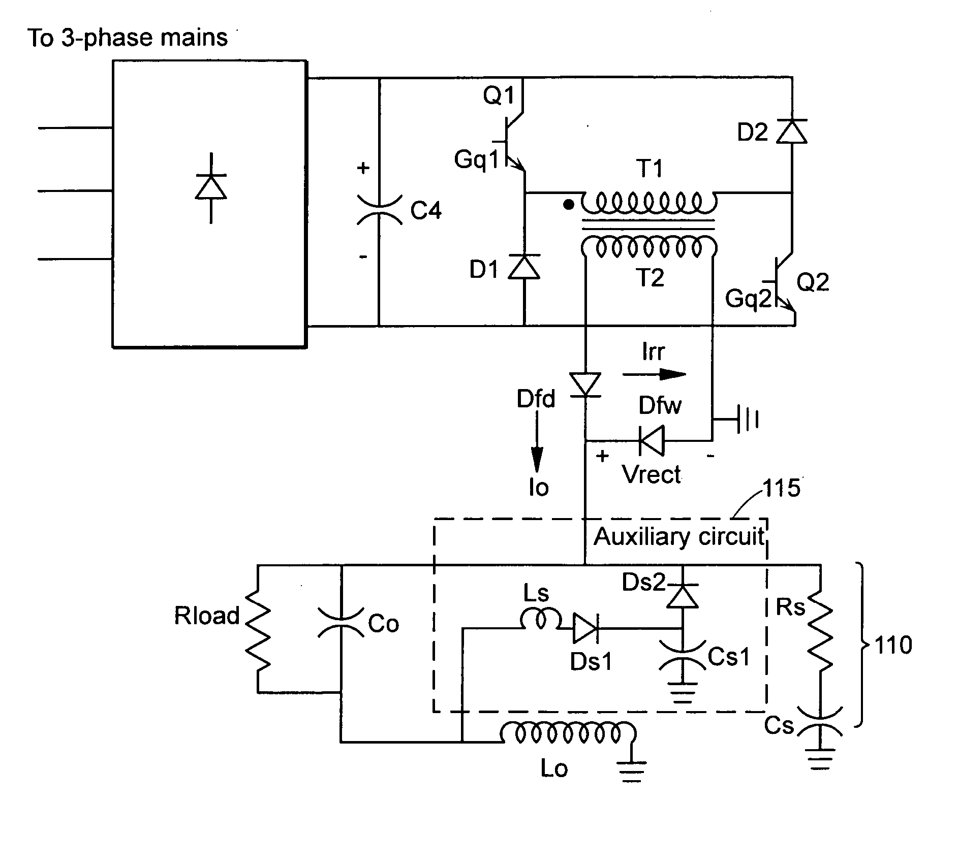
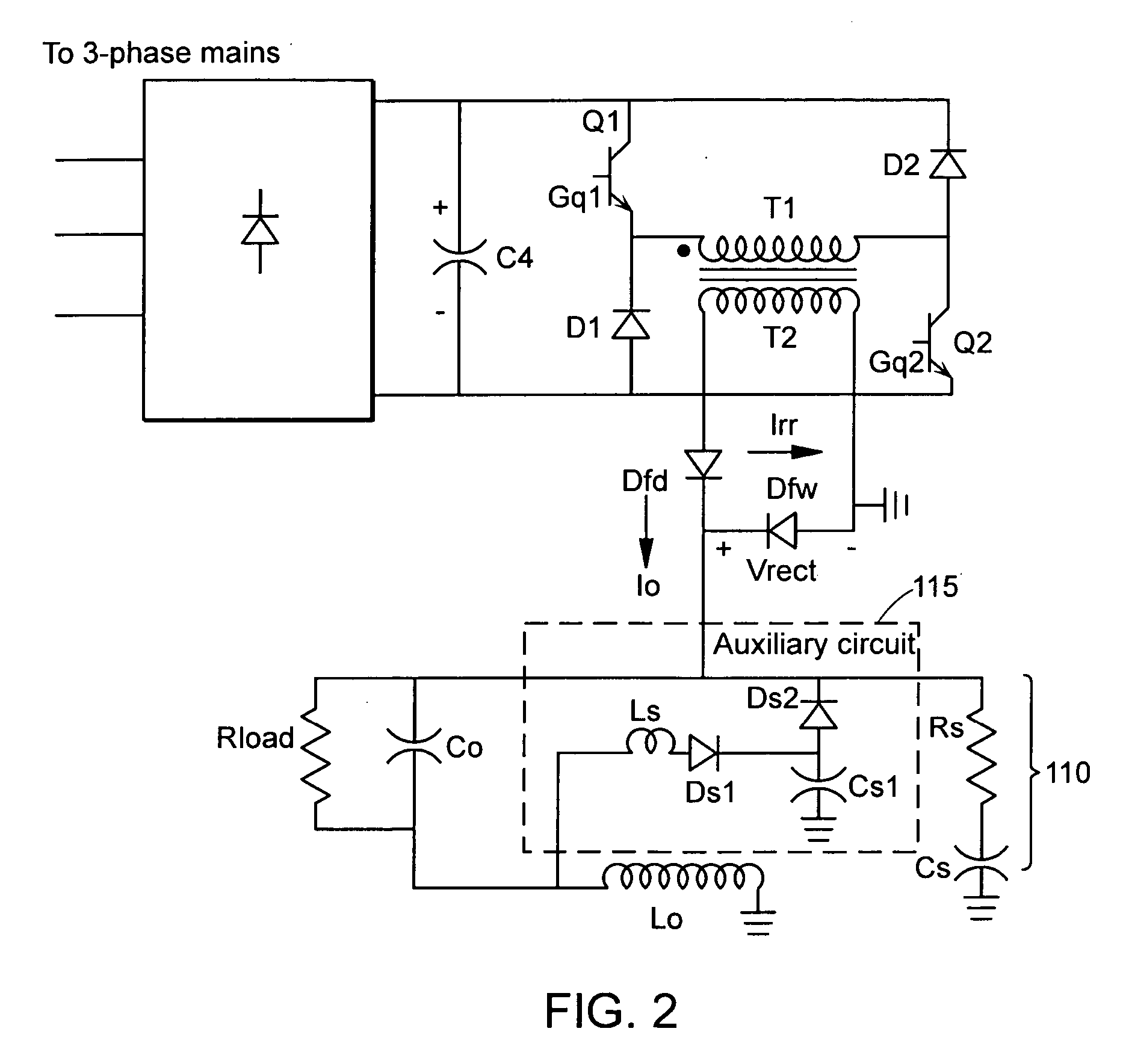
[0051]FIG. 2 is a schematic circuit diagram of a two-switch forward converter power supply including a snubber circuit according to a The snubber circuit can be implemented in power supply units of any number of applications, including high temperature metal processing such as plasma cutting, welding and laser processing. As shown, the snubber circuit includes a dissipative snubber circuit 110 and a non-dissipative auxiliary snubber circuit 115. The dissipative snubber circuit 110 can be a conventional R-C snubber circuit that includes a resister Rs in series with a capacitor Cs connected across the free-wheeling diode Dfw. The non-dissipative snubber circuit 115 is an auxiliary circuit that can include an inductor Ls, capacitor Cs1 and diodes Ds1, Ds2.

Snubber Circuit Operation During Energy Delivery Period

[0052] Referring to FIG. 2, the energy (or forward power) delivery period begins with the initiation of a reverse recovery period. At the beginning of the reverse recovery peri...

second embodiment

[0089]FIG. 11 is a schematic circuit diagram of a two-switch forward converter power supply including a snubber circuit according to a In this embodiment, the snubber circuit is similar to the snubber circuit of FIG. 2, except that a zener diode Zd is coupled in parallel to snubber capacitor Cs1. The function of the zener diode is to clamp the voltage across the snubber capacitor Cs1 and thereby limit the maximum rectifier voltage stress. This enables further reduction in the power rating of the snubber resister Rsnub, because the zener diode now provides an alternate means for dissipating power.

third embodiment

[0090]FIG. 12 is a schematic circuit diagram of a two-switch forward converter power supply including a snubber circuit according to a In this embodiment, the snubber circuit is similar to the snubber circuit of FIG. 2, except that the resonant auxiliary snubber circuit 415 includes an additional winding Lp that is coupled to the resonant inductor Ls. Simulations have shown that reducing the resonant inductor value Ls with increase in output voltage Vo helps to reduce the variation in peak output rectifier voltage stress (Vrect(pk)) due to changes in Vo. Here, the value of inductor Ls is determined by the current flowing through its additional winding Lp and Vo. This current saturates the inductor core at high Vo and reduces its value in the process. Table 5 contains a summary of the simulation results with inductor Ls replaced by an inductor whose value varies in the ratio 3:1 over the entire output voltage range. The results show a reduction in output rectifier voltage stress (vr...


PUM

PropertyMeasurementUnit
Poweraaaaaaaaaa
Poweraaaaaaaaaa
Poweraaaaaaaaaa

Abstract

A snubber circuit for absorbing reverse recovery current in a power supply is featured comprising a dissipative snubber circuit and a non-dissipative snubber circuit coupled in parallel to a source of reverse recovery current and a load. The dissipative snubber circuit is capable of dissipating a first amount of reverse recovery current from the reverse recovery current source and the non-dissipative snubber circuit recovering a second amount of reverse recovery current from the reverse recovery current source, resulting in the reverse recovery current being absorbed with reduced power dissipation.

Description

RELATED APPLICATIONS [0001] This application claims the benefit of U.S. Provisional Application No. 60 / 701,570, filed on Jul. 23, 2005. The entire teachings of the above application(s) are incorporated herein by reference.BACKGROUND [0002] R-C snubber circuits are used to absorb the energy associated with a reverse recovery current of a rectifier diode and limit the associated voltage spike across it. FIG. 1 is a schematic circuit diagram illustrating a conventional R-C snubber circuit as applied to a two-switch forward converter power supply. At the beginning of the energy delivery period, transistors Q1 and Q2 are initially turned on causing a load current Io to flow through forward diode D9 and the freewheeling diode D10 to turn off. As the freewheeling diode D10 turns off, a reverse recovery current Irr conducts through diode D10, resulting in associated energy building up in the leakage inductance of the transformer secondary. [0003] After the freewheeling diode D10 turns off, ...

Claims


Application Information

Patent Timeline
IPC IPC(8): H02H3/00
CPCB23K10/00H02M1/34Y02B70/1491H02M2001/346H02M3/3353H02M1/346Y02B70/10
Inventor KAMATH, GIRISH R.
Owner HYPERTHERM INC
Why Eureka
Try Eureka