Eureka AIR delivers breakthrough ideas for toughest innovation challenges, trusted by R&D personnel around the world.

Method for controlling temperature of terminal and terminal supporting the same

a terminal and temperature control technology, applied in pulse generators, pulse techniques, instruments, etc., can solve the problems of terminal malfunction, reduced heat dissipation space, and difficulty in emitted heat, so as to achieve efficient and stably the effect of operation

Active Publication Date: 2014-09-30
SAMSUNG ELECTRONICS CO LTD
View PDF16 Cites 6 Cited by
  • Summary
  • Abstract
  • Description
  • Claims
  • Application Information

AI Technical Summary

Benefits of technology

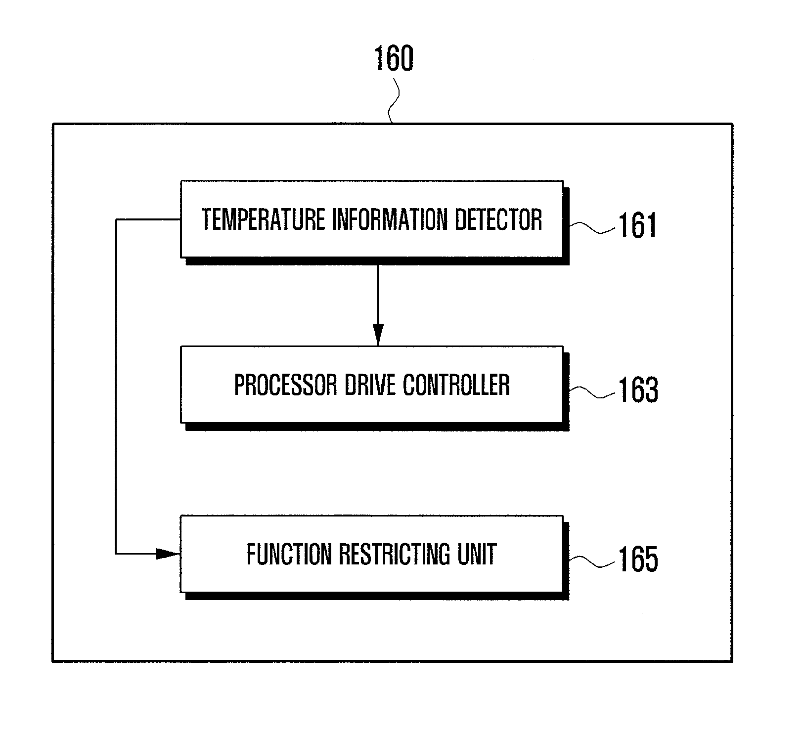
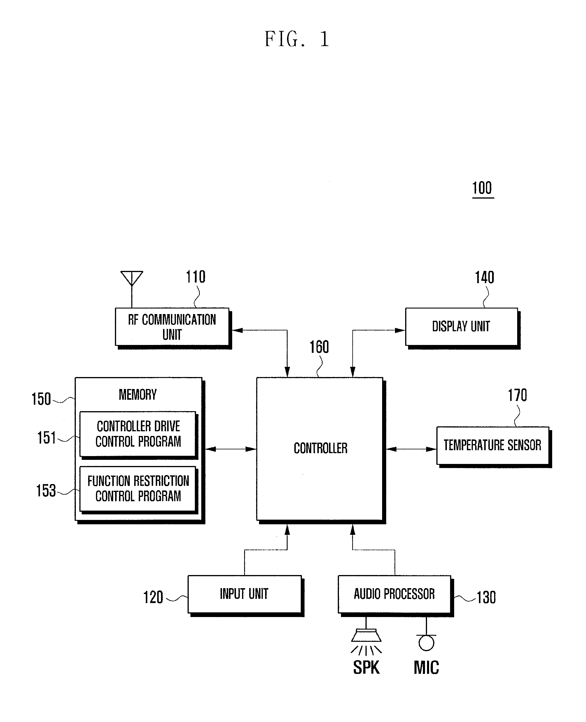
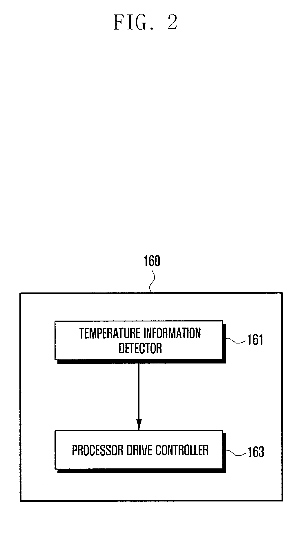
[0006]Aspects of the present invention are to address at least the above-mentioned problems and / or disadvantages and to provide at least the advantages described below. Accordingly, an aspect of the present invention is to provide a method for controlling a temperature of a terminal supporting such that temperature control of the terminal may be efficiently and stably performed, and a terminal supporting the same.
[0007]Another aspect of the present invention is to provide a method for controlling a temperature of a terminal that limits diving of a controller of the terminal such that a temperature of the terminal is reduced or is converged to a constant temperature, and a terminal supporting the same.

Problems solved by technology

When the density of the internal components of the terminal is increased, the space available for dissipating heat during operation of the terminal is reduced such that emission of heat becomes difficult.
When a temperature of the terminal increases according to accumulation of heat of the internal component of the terminal, the terminal may malfunction.
When the temperature of the terminal increases significantly, a battery or internal components may be damaged.
Furthermore, in an environment having a high ambient temperature, the ambient temperature influences the temperature of the terminal, negatively impacting the stability of the terminal.

Method used


Image

  • Method for controlling temperature of terminal and terminal supporting the same
  • Method for controlling temperature of terminal and terminal supporting the same
  • Method for controlling temperature of terminal and terminal supporting the same

Examples


Embodiment Construction

[0021]The following description with reference to the accompanying drawings is provided to assist in a comprehensive understanding of exemplary embodiments of the as defined by the claims and their equivalents. It includes various specific details to assist in that understanding, but these are to be regarded as merely exemplary. Accordingly, those of ordinary skill in the art will recognize that various changes and modifications of the embodiments described herein can be made without departing from the scope and spirit of the invention. In addition, descriptions of well-known functions and constructions may be omitted for clarity and conciseness.

[0022]The terms and words used in the following description and claims are not limited to the bibliographical meanings, but are merely used by the inventor to enable a clear and consistent understanding of the invention. Accordingly, it should be apparent to those skilled in the art that the following description of exemplary embodiments of ...


PUM


Abstract

A method for controlling a temperature of a terminal and a terminal supporting the same are provided. A terminal supporting temperature control includes a temperature sensor for detecting a temperature of the terminal, and a controller for performing at least one of a first throttle procedure including driving the controller with a first preset driving frequency when the temperature of the terminal detected by the temperature sensor is a first preset temperature, and driving the controller with a second driving frequency higher than the first driving frequency when the temperature of the terminal is reduced to a second preset temperature lower than the first preset temperature, and a second throttle procedure including driving the controller with the first preset driving frequency for a first time, and driving the controller with the second driving frequency higher than the first driving frequency for a second time after the first time elapses.

Description

PRIORITY[0001]This application claims the benefit under 35 U.S.C. §119(a) of a Korean patent application filed on Jul. 29, 2011 in the Korean Intellectual Property Office and assigned Serial No. 10-2011-0076215, the entire disclosure of which is hereby incorporated by reference.BACKGROUND OF THE INVENTION[0002]1. Field of the Invention[0003]The present invention relates to temperature control of a terminal. More particularly, the present invention relates to a method for controlling a temperature of a terminal and a terminal supporting the same that restrict driving of a controller or functions of the terminal for temperature control of the terminal so that the terminal may maintain stable operations.[0004]2. Description of the Related Art[0005]With rapid development of technology, terminals have been developed to support various functions, such as image call, electronic organizer function, Internet function in addition to voice calls. The terminal supports a call function, a voice ...

Claims


Application Information

Patent Timeline
Patent Type & Authority Patents(United States)
IPC IPC(8): H01L35/00G05D23/19
CPCG05D23/1951G05D23/1919G06F1/203G06F1/206G06F1/3206G06F1/324Y02D10/00G05D23/19H04B1/40
Inventor PARK, KI YEONJANG, SE YOUNGYUN, CHUL EUN
Owner SAMSUNG ELECTRONICS CO LTD
Why Eureka
Eureka Blog
Learn More