Paper conveyance device and printer

a technology of paper conveyance and printer, which is applied in the direction of printing and other printing apparatus, can solve the problems of drop in print quality, inability to maintain the appropriate gap between the printhead and the recording medium, and poor print quality, so as to prevent a drop in print quality

Inactive Publication Date: 2014-10-14
SEIKO EPSON CORP
View PDF7 Cites 1 Cited by
  • Summary
  • Abstract
  • Description
  • Claims
  • Application Information

AI Technical Summary

Benefits of technology

[0014]With a paper conveyance device according to these aspects of the invention, puckering of the conveyed continuous paper is gradually deflated and dispersed to a number of smaller bulges by the first rib of the paper conveyance device located in the middle of the paper width, and by the second ribs and third ribs that are gradually shorter in the conveyance direction and disposed with a specific gap between ribs in the direction perpendicular to the conveyance direction. As a result, even if bubbles or wrinkles occur in the paper, the height thereof can be reduced and spread evenly. A suitable gap can therefore be maintained between the printhead and the continuous paper. A drop in print quality can therefore be prevented.
[0029]A printing device according to this aspect of the invention can prevent a drop in print quality caused by puckering, wrinkling, or creasing of the continuous paper.

Problems solved by technology

If the conveyed recording medium is wrinkled or puckered (does not lie flat), a desirable relationship between the printhead and the recording medium is not maintained and print quality may suffer.
When printing to such recording media with a printer such as an inkjet printer, an appropriate gap cannot be maintained between the printhead and the recording medium, and print quality drops.
In extreme cases the recording medium may touch the printhead, and normal printing may not be possible.
In addition, when a paper feed mechanism with rollers is disposed near the printhead and the pressure roller is used to correct such problems, the roller may crush the wrinkled part and create a creased wrinkle.

Method used


Image

  • Paper conveyance device and printer
  • Paper conveyance device and printer
  • Paper conveyance device and printer

Examples


embodiment 1

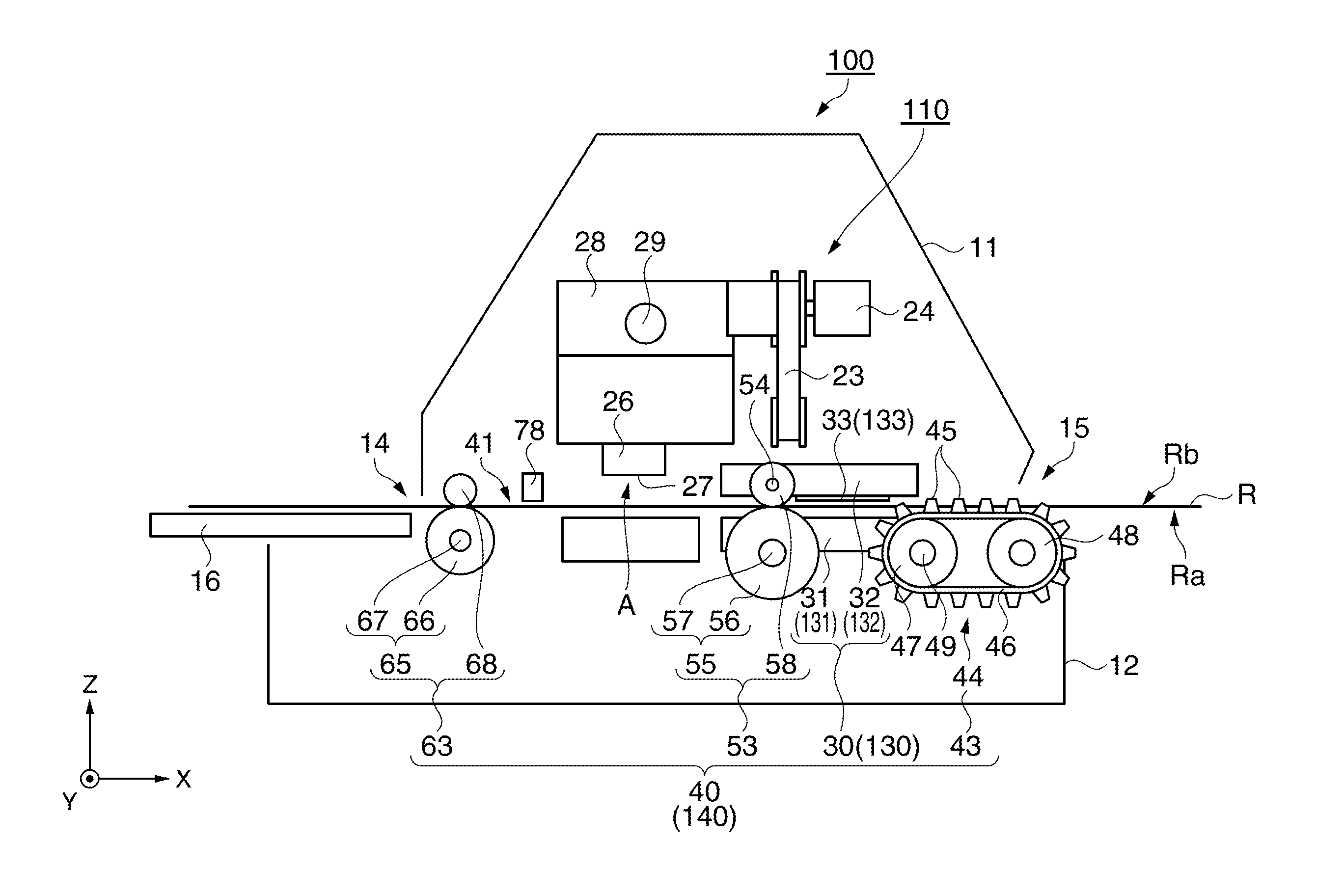
[0049]The configuration of a paper conveyance device according to a first embodiment of the invention is described next with reference to FIG. 3 to FIG. 5. FIG. 3 schematically shows the configuration of the paper conveyance device, and FIG. 4 a guide unit according to the first embodiment of the invention. FIG. 4A is a plan view of the area around the guide unit, and FIG. 4B is a side view of the area around the guide unit. FIG. 5 shows the configuration of the power transfer mechanism of the paper feed direction. Note that the x-axis, y-axis, and z-axis shown in FIG. 3 to FIG. 5 denote the same directions as the x-axis, y-axis, and z-axis shown in FIG. 1. Note also that this paper conveyance device conveys continuous paper R that has sprocket holes.

[0050]As shown in FIG. 3, the paper conveyance device 40 has a paper conveyance path 41, a guide unit 30, a first conveyance mechanism 43, a second conveyance mechanism 53, a third conveyance mechanism 63, and a power transfer mechanism...

embodiment 2

[0086]A paper conveyance device according to a second embodiment of the invention is described next with reference to FIG. 3, FIG. 5, and FIG. 9. FIG. 9 describes a guide unit according to a second embodiment of the invention. Note that like parts and content in this and the first embodiment described above are identified by like reference numerals, and further description thereof is omitted or simplified.

[0087]The paper conveyance device 140 according to the second embodiment of the invention is the same as the paper conveyance device 40 of the first embodiment except that the configuration of the guide unit 130 differs from the guide unit 30 described above. More specifically, this paper conveyance device 140 includes the paper conveyance path 41, a guide unit 130, first conveyance mechanism 43, second conveyance mechanism 53, third conveyance mechanism 63, and power transfer mechanism 70 (see FIG. 5). Similarly to the paper conveyance device 40 of the first embodiment, the paper ...


PUM


Abstract

A paper conveyance device for a printing device that prints information using a printhead on conveyed continuous paper R, including a paper conveyance mechanism that holds and conveys the continuous paper to the print area of the printhead, and a guide unit that has two guide surfaces facing the conveyed continuous paper. The guide unit has a plurality of ribs that are disposed to at least one of the two guide surfaces with a specific gap therebetween in the direction perpendicular to the conveyance direction, protrude to the continuous paper side, and extend in the conveyance direction. The rib located in the middle of the width of the conveyed continuous paper being the longest of the plural ribs in the conveyance direction, and the length in the conveyance direction of the other ribs becoming gradually shorter with proximity to the sides of the continuous paper width.

Description

BACKGROUND[0001]1. Technical Field[0002]The present invention relates to a paper conveyance device for recording media on which information is recorded, and to a printer having the paper conveyance device.[0003]The present application claims priority based on and incorporates by reference the entire contents of Japanese Patent Application No. 2010-202774 filed in Japan on Sep. 10, 2010, and No. 2010-202775 filed on Sep. 10, 2010.[0004]2. Related Art[0005]Printers are used for recording information in business and many other fields. As a result, many different kinds of recording media are also used for recording information. These recording media include multipart forms composed of plural sheets. This type of recording medium is typically supplied as fanfold paper. Fanfold paper has sprocket holes (conveyance holes) formed in the conveyance direction, is perforated between each page so that the pages can be easily separated, and is stored in a stack with the pages alternately folded ...

Claims


Application Information

Patent Timeline
Patent Type & Authority Patents(United States)
IPC IPC(8): B41J2/01B41J11/06B41J15/04
CPCB41J11/06B41J15/04
Inventor MITSUYA, TOSHIYUKI
Owner SEIKO EPSON CORP
Why Eureka
Try Eureka