Steam/water static mixer injector for extrusion equipment

a technology of extrusion equipment and injectors, which is applied in the directions of feeding-stuffs, applications, transportation and packaging, etc., can solve the problems of contamination, significant quantity of steam, and complicated apparatuses that are difficult to service and clean, and achieve the effect of reducing or eliminating the plugging of fluid injection apparatuses

Active Publication Date: 2014-10-14
WENGER MFG LLC
View PDF76 Cites 20 Cited by
  • Summary
  • Abstract
  • Description
  • Claims
  • Application Information

AI Technical Summary

Benefits of technology

[0014]In order to minimize or eliminate plugging of the fluid injection apparatus, the axial distance between the valve outlet and the inner surface of the preconditioner housing should be less than about 3 inches, advantageously less than about 1 inch, and most preferably less than about one-half inch. Similarly, the diameter of the fluid-conveying structure of the injection apparatus should be relatively large, preferably at least about 1 inch. The combination of the large diameter fluid conveying-structure together with the short valve injection distance assures essentially plug-free operation of the preconditioner.

Problems solved by technology

This complicated apparatus can be difficult to service and clean, and requires sophisticated manual operator control to assure proper moisturization at the different injection locations.
These conventional preconditioners tend to generate and vent a significant quantity of steam during use thereof.
This is a serious problem for processors, owing to the fact that this escaping hot steam can readily mix with food particulates, creating a contamination problem as the materials coat the extrusion system components and the adjacent environment.
This contamination is aesthetically unpleasant, and can create serious microbiological contamination problems as well.
Moreover, the evolution of excess steam is a very inefficient waste of thermal energy.
As such, it is quite common for the injectors to become partially or completely plugged during operation of the preconditioners, requiring down time and maintenance / cleanup.
Many of these problems are duplicated where extruders are equipped with conventional injectors, although not usually to the same extent as preconditioners.
Nonetheless, it can be difficult to control and continuously operate an extruder where injection / contamination issues are faced.

Method used


Image

  • Steam/water static mixer injector for extrusion equipment
  • Steam/water static mixer injector for extrusion equipment
  • Steam/water static mixer injector for extrusion equipment

Examples


Embodiment Construction

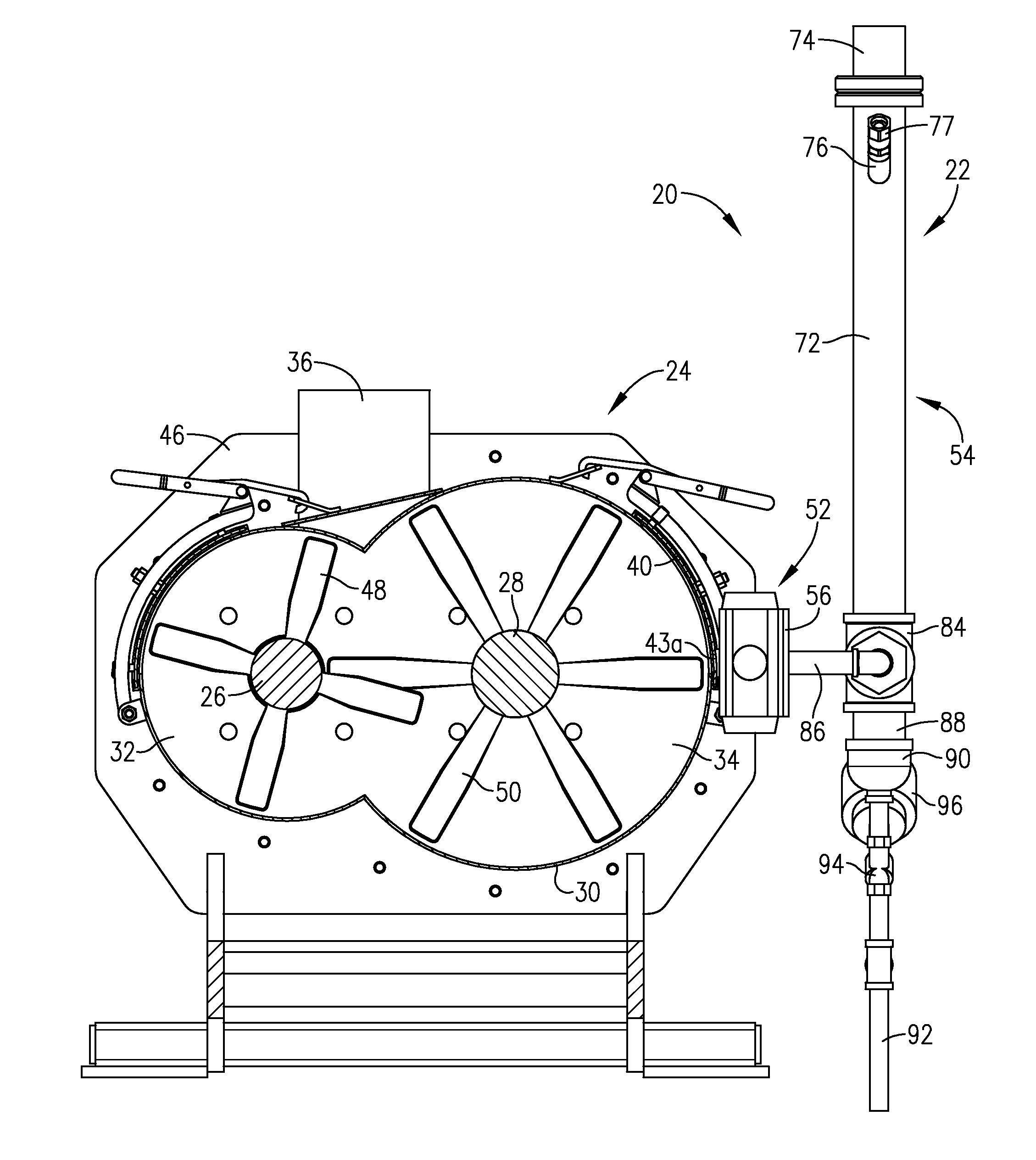
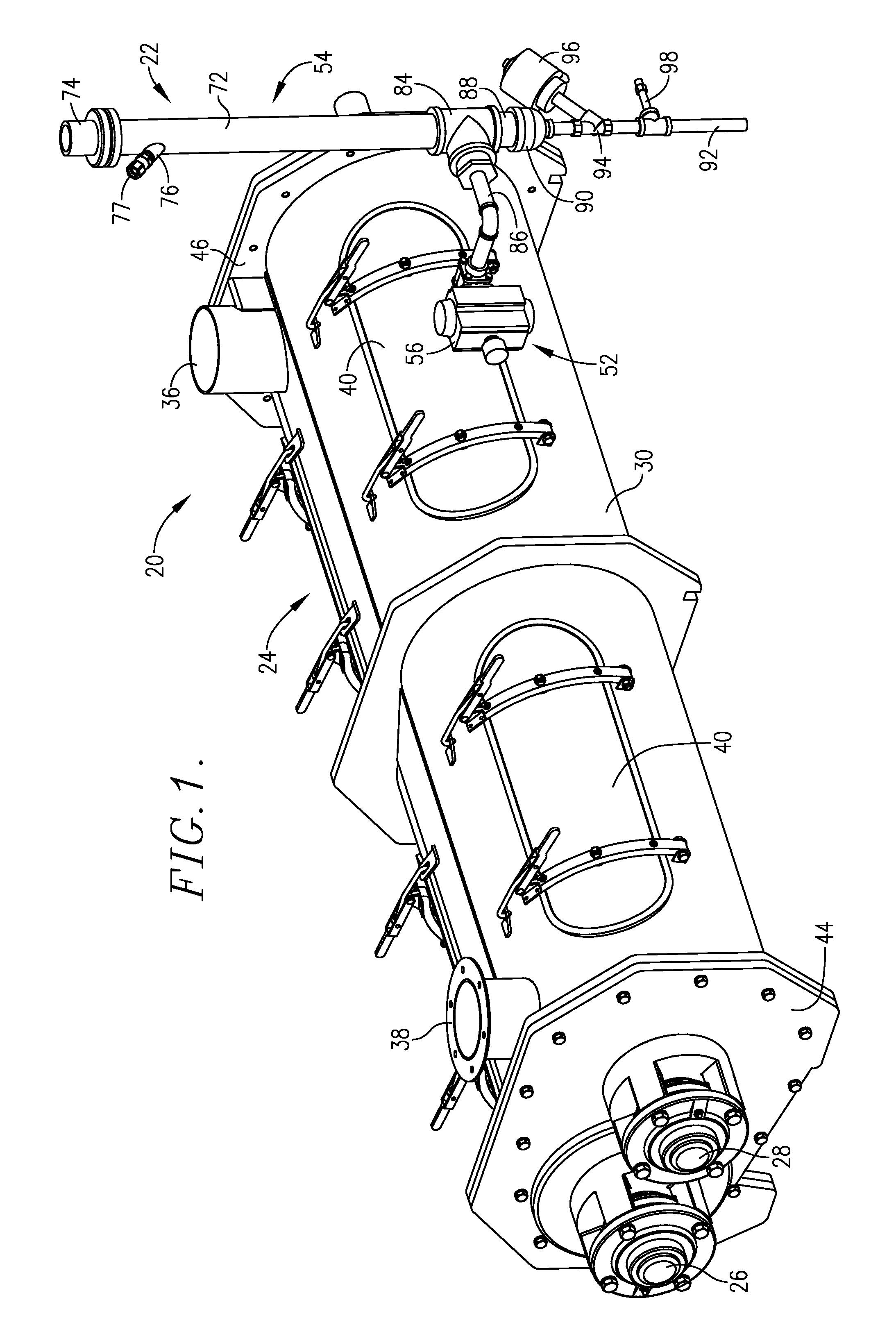
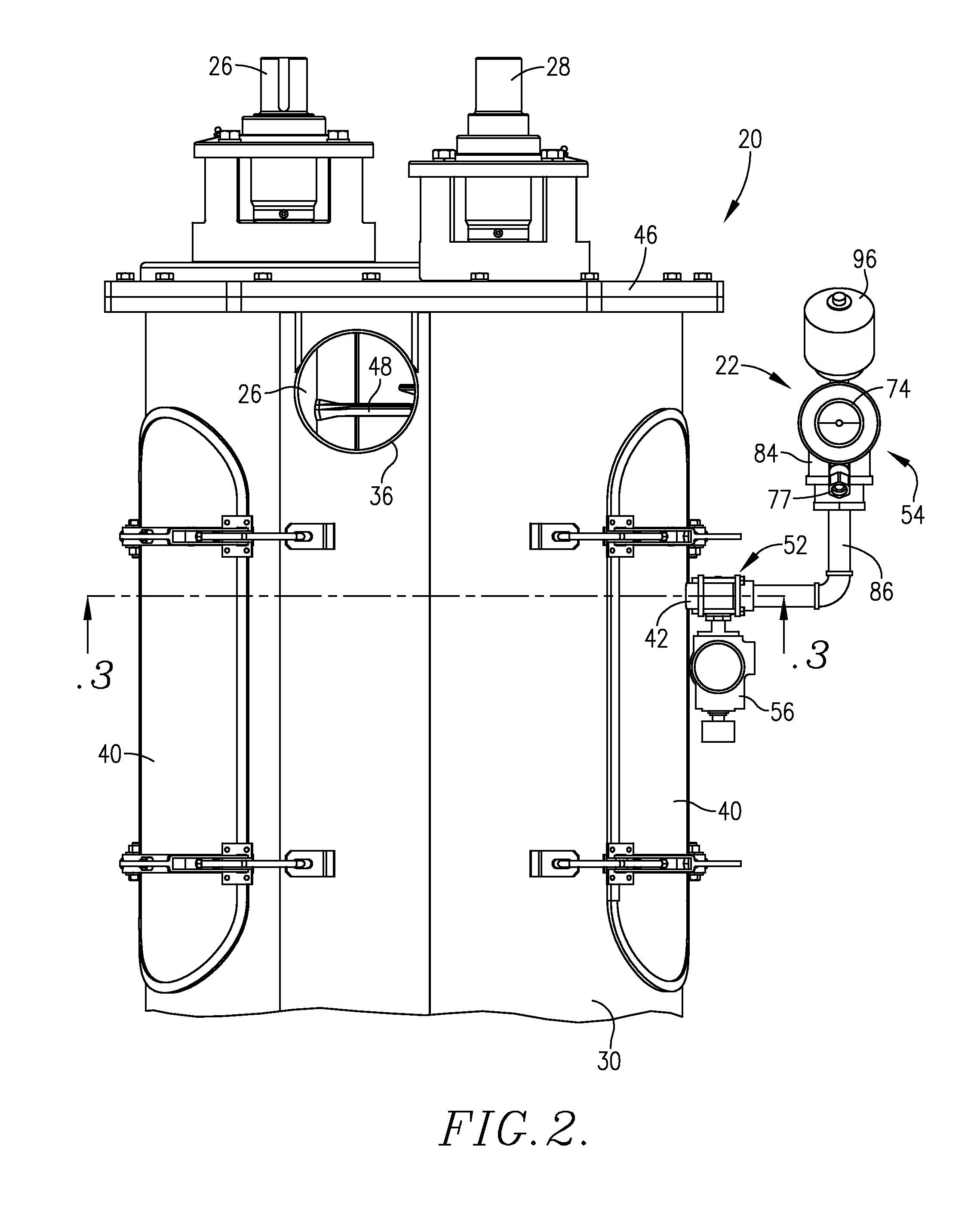
[0028]Turning now to FIGS. 1-4, a preconditioner 20 is illustrated, equipped with a composite fluid injection assembly 22 mounted thereon for delivery of mixed fluids, such as steam and water, to the interior of the preconditioner. The preconditioner is of the type described in U.S. Pat. No. 7,906,166, which is fully and completely incorporated by reference herein. Broadly, the preconditioner 20 includes an elongated mixing housing 24 with a pair of parallel, elongated, axially-extending, rotatable mixing shafts 26 and 28 within and extending along the length thereof. The shafts 26, 28 are operably coupled with individual, digitally controlled, variable speed / direction drive devices (not shown). The preconditioner 20 is adapted for use with a downstream processing device such as an extruder or pellet mill, and is used to moisturize and partially cook comestible materials, such as human foods or animal feeds.

[0029]In more detail, the housing 24 has an elongated, transversely arcuate ...


PUM

PropertyMeasurementUnit
axial distanceaaaaaaaaaa
diameteraaaaaaaaaa
lengthsaaaaaaaaaa

Abstract

Apparatus (20) for injection of fluid into extrusion system components such as a preconditioner (24) or extruder (100) is provided, preferably as a composite assembly including a fluid injection valve (52) and an interconnected static mixer section (54). Alternately, use may be made of the fluid injection valve (52) or static mixer section (54) alone. The invention greatly simplifies the fluid injection apparatus used in extrusion systems, while giving more efficient absorption of thermal energy with a minimum of environmental contamination, and the ability to inject multiple streams into the extrusion systems.

Description

CROSS-REFERENCE TO RELATED APPLICATION[0001]This application is a continuation of identically titled pending application Ser. No. 13 / 937,573 filed Jul. 9, 2013, and incorporated herein in its entirety.BACKGROUND OF THE INVENTION[0002]1. Field of the Invention[0003]The present invention is broadly concerned with improved apparatus for the injection of plural fluids into extrusion system processing components, such as preconditioners and extruders. More particularly, the invention is concerned with such apparatus, alone or in combination with extrusion system processing components, which include injector valves, preferably with interconnected static mixer sections, to efficiently inject steam / water mixtures (and other optional fluids, if desired) using greatly simplified equipment.[0004]2. Description of the Prior Art[0005]Extrusion cooking systems have long been used for the processing of various types of comestible products, such as human foods or animal feed. Such systems have a nu...

Claims


Application Information

Patent Timeline
Patent Type & Authority Patents(United States)
IPC IPC(8): B01F15/02B29C48/29B29C48/295
CPCB29C2947/92504B01F13/1022B01F7/00B29C47/1018B01F7/022B01F5/0605B29B7/46B29B7/7461B29B7/801B01F13/103B01F7/042B29B7/728B29C47/0004B29B7/88B29B7/488B29C2947/92209B29B7/40B29C2947/9259A23P1/12A23N17/005A23N17/007B01F5/0615B29B7/72B01F2005/0637B01F15/0201B29B7/60B01F27/2322B01F27/702B01F35/7179A23P30/20B29C48/287B29C48/022B29C48/29B29C48/295B29C48/297B29C2948/9259B29C2948/92209B29C2948/92504A23N17/004B29B7/7485B01F25/43141B01F25/431972B01F27/62B01F33/8212B01F33/813B29B7/94B01F25/423B01F27/00B01F35/71B01F35/2115B01F2101/06A23L5/13A23V2002/00
Inventor VANDALSEM, SCOTT EUGENESTREIT, BRIAN D.
Owner WENGER MFG LLC
Why Eureka
Try Eureka