Device for positioning an implant

a technology for implant devices and implants, applied in the field of implant equipment, can solve the problems of inconvenient single-use installation equipment, inability to quickly mount and demount implants, and inability to use locking equipment for single-use installation equipment, etc., and achieve the effect of rapid implant engagement and releas

Active Publication Date: 2014-11-04
SAFE ORTHOPAEDICS SAS
View PDF11 Cites 13 Cited by
  • Summary
  • Abstract
  • Description
  • Claims
  • Application Information

AI Technical Summary

Benefits of technology

[0012]The invention aims to remedy the problems of the prior art by proposing implant installation equipment that is not very invasive, allowing precise implant installation as well as rapid implant engagement and release.
[0014]Another aim of the invention is to propose installation equipment that is strong and of optimum size, offering reliable holding of the implant and responding to miniaturisation of the implants and surgical instruments.
[0016]Thus the equipment obtained when the gripping instrument and the locking element are assembled offers improved mechanical strength in respect of bending and twisting and ensures good fixing of the implant on the instrument. Moreover, controlling the portions of the instrument providing the gripping of the implant or release thereof by means of an internal element makes it possible to limit the overall size.
[0020]According to an advantageous embodiment, the means of attaching the locking element comprise projections in the form of a dovetail able to be inserted in grooves of complementary shape provided in the housing, and vice versa. This makes it possible to offer a bilateral sliding connection. Moreover, the equipment obtained when the gripping instrument and the locking element are assembled offers improved mechanical strength in terms of bending and twisting and ensures holding of the implant.

Problems solved by technology

Such equipments do not however allow rapid mounting and demounting of the implant because of the screwing and unscrewing operations.
A second drawback is that locking by means of a threaded part makes it necessary, once the implant is placed, to remove the equipment in order to continue the surgical intervention.
A first drawback is that the locking equipment used is not suitable for single-use installation equipment.
The arms of the single-use equipment are in fact more fragile through the nature of the material from which the equipment is produced.
However, locking the implant by placing a locking piece around the arms accentuates this fragility.
A second drawback is that, apart from the fragility that it confers on the equipment, the presence of a piece external to the tubular body of the equipment leads to relatively bulky equipment.
Another drawback is that locking by means of an external piece is suitable only for an instrument with a straight shape.
It cannot be used with equipment of complex shape, which limits the field of application.

Method used


Image

  • Device for positioning an implant
  • Device for positioning an implant
  • Device for positioning an implant

Examples


Embodiment Construction

)

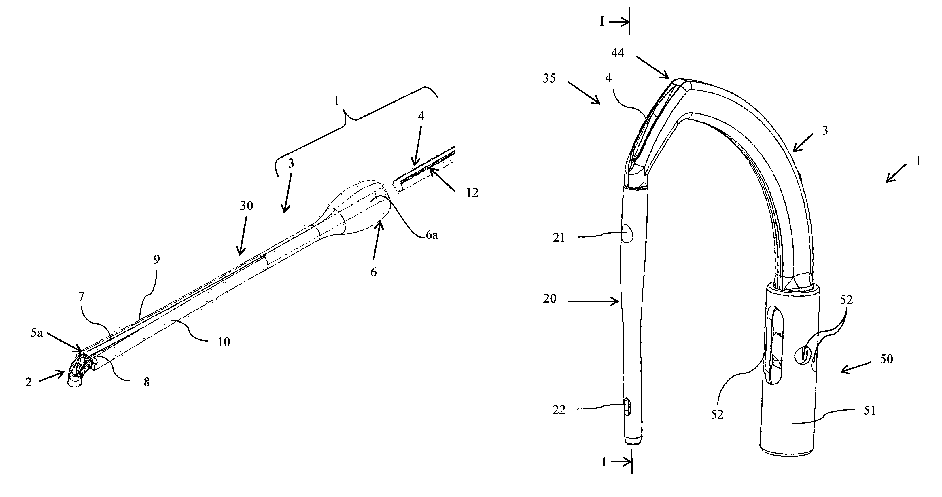
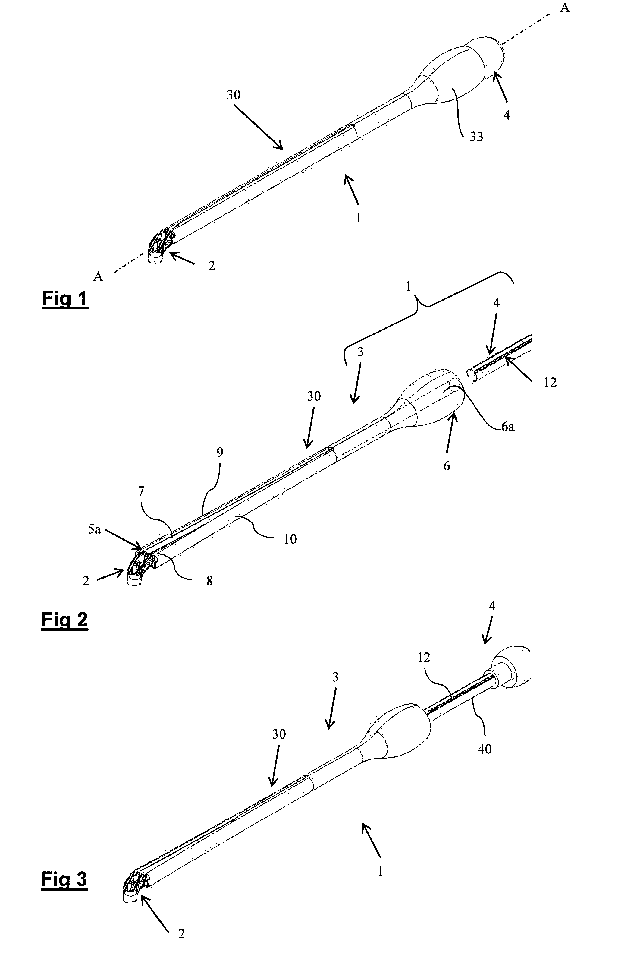
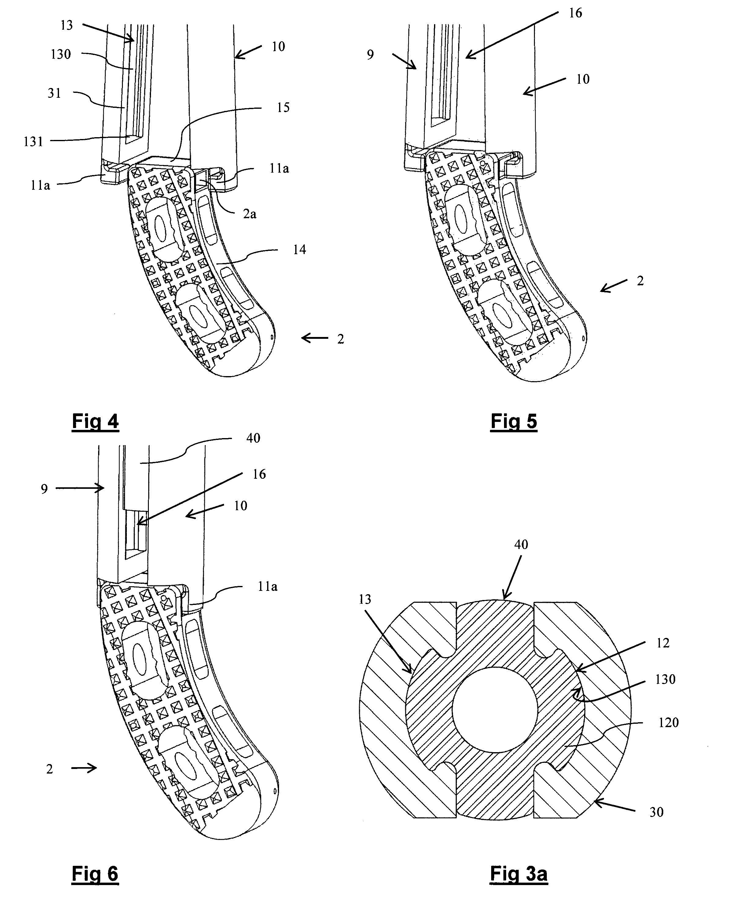
[0054]In relation to FIGS. 1 to 6, an item of equipment 1 for placing an intersomatic cage 2 between two rachidian vertebrae is described.

[0055]The form of the cage used with the equipment according to the invention is not limited to the form illustrated in FIGS. 1 to 6. This is because the form of a cage varies according to the approaches by means of which the surgical intervention takes place (anterior, posterior or lateral approaches) and according to the type of region of the spinal column in which the cage is implanted (cervical, thoracic or lumbar regions). However, and as will be seen below, the cage intended to be associated with the equipment comprises specific means enabling it to be gripped by the equipment in question.

[0056]The equipment 1 for placing an intersomatic cage 2 comprises a first element forming an instrument 3 for gripping the cage 2 and a second element forming a locking element 4 enabling the cage 2 to be held by the instrument when it is in engagement wi...


PUM


Abstract

Equipment for placing an implant comprising an instrument for gripping the implant comprising two portions able to adopt a position of holding the implant and an open position allowing gripping or release of the implant once the latter is implanted, and an element for locking the portions in the holding position, the locking element comprising an attachment device arranged to come into engagement with a complementary attachment device provided in a reception housing formed by the portions in the implant-holding position, the attachment device and the complementary attachment device forming a sliding connection.

Description

CROSS REFERENCE TO RELATED APPLICATION[0001]This application claims the priority of the French patent application no 09 / 06369 filed on Dec. 28, 2009 whose contents are fully incorporated by reference.BACKGROUND[0002]The invention concerns equipment for placing an implant.[0003]The equipment is intended in particular, but not exclusively, for placing an intersomatic cage, a femoral nail, a rachidian pedicle screw, a disc prosthesis or a rachidian osteosynthesis plate.[0004]In a manner that is conventional per se, the equipments used for placing an implant comprises a threaded part able to cooperate with a tapped part provided in the implant. Patent applications WO 96 / 22747 and FR 2668360 describe such equipments. Thus mounting the implant on the equipment generally takes place by engaging, by screwing, the threaded part in the tapped bore of the implant. Once the implant is positioned in the planned location, the installation equipment (or placement equipment) is released from the im...

Claims


Application Information

Patent Timeline
Patent Type & Authority Patents(United States)
IPC IPC(8): A61F2/00A61B17/60A61B17/58A61B19/02A61B17/70
CPCA61B19/026A61B2019/0278A61B19/0271A61B17/7079A61B17/7076A61B17/7085A61B50/30A61B50/33A61B2050/3008
Inventor PETIT, DOMINIQUE
Owner SAFE ORTHOPAEDICS SAS
Why Eureka
Try Eureka