
Antenna module and electronic device with the same

a technology of electronic devices and antenna modules, applied in the field of antenna modules, can solve problems such as difficulty in carrying, and achieve the effect of convenient for users

Active Publication Date: 2014-11-11
ASUSTEK COMPUTER INC
View PDF17 Cites 0 Cited by
  • Summary
  • Abstract
  • Description
  • Claims
  • Application Information

AI Technical Summary

Benefits of technology

The patent describes an electronic device with an antenna that can be extended from the device or hidden within it. When the antenna is protected in the device, it acts as an inverted-F antenna. When the antenna is extended, it acts as a monopole antenna. This allows the device to effectively receive signals, whether it is placed in a user's hand or on a table. The technical effect is that the device can operate in different modes to optimize signal reception.

Problems solved by technology

However, the extended bar antenna may be too space occupied, and cause difficulty for carrying.

Method used


Image

  • Antenna module and electronic device with the same
  • Antenna module and electronic device with the same
  • Antenna module and electronic device with the same

Examples


second embodiment

[0025]Please refer to FIG. 5 and FIG. 6. FIG. 5 is a top view showing an antenna body 160 and a conducting element 164′ in the invention. FIG. 6 is a side view showing the antenna body 160 and the conducting element 164′ in FIG. 5. As shown in FIG. 5 and FIG. 6, the conducting element 164 is also a resilient plate. As shown in FIG. 6, when the antenna body 160 moves towards the direction X along an axis, the antenna body 160 presses the conducting element 164′ in direction Z to contact and conduct with the conducting element 164′. At the time, the conducting element 164′ is below the antenna body 160.

third embodiment

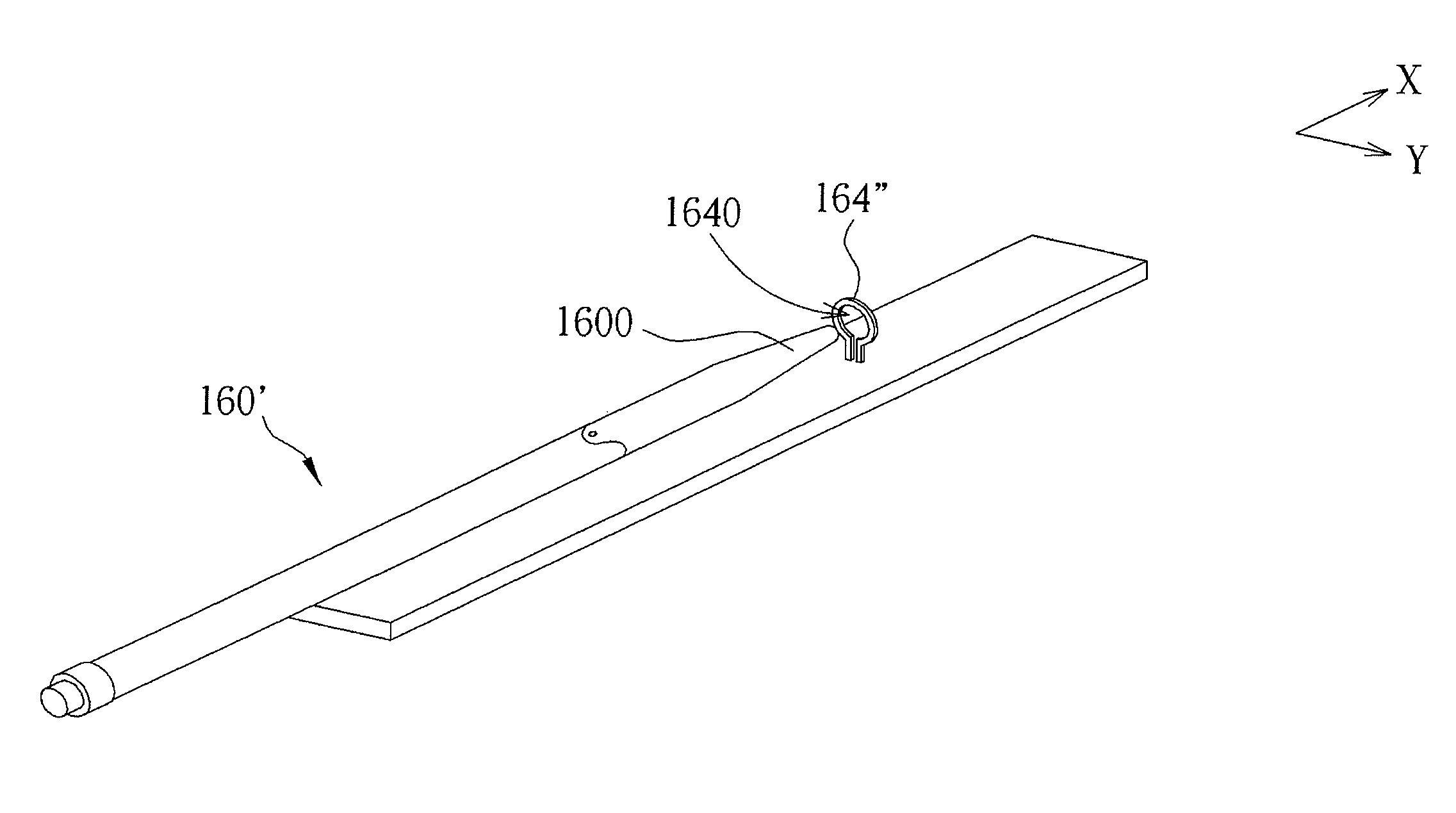
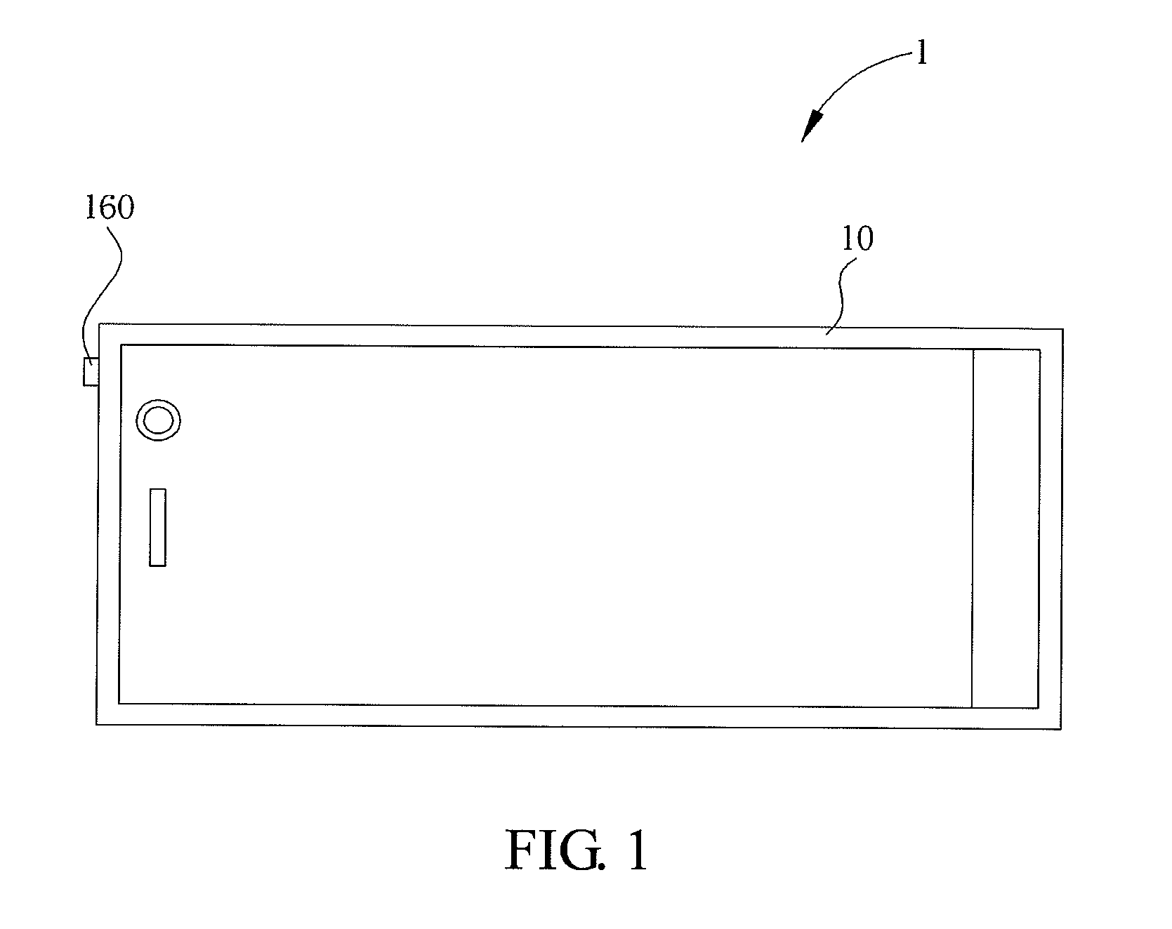
[0026]FIG. 7 is a schematic diagram showing an antenna body 160′ and a conducting element 164″ in a As shown in FIG. 7, the antenna body 160′ includes a tapered end 1600, and the conducting element 164″ has a through hole 1640. When the antenna body 160′ is at the first position (that is, the antenna body 160′ is hidden in the casing 10 of the electronic device 1), the tapered end 1600 engages the through hole 1640 to contact and conduct with the conducting element 164″.

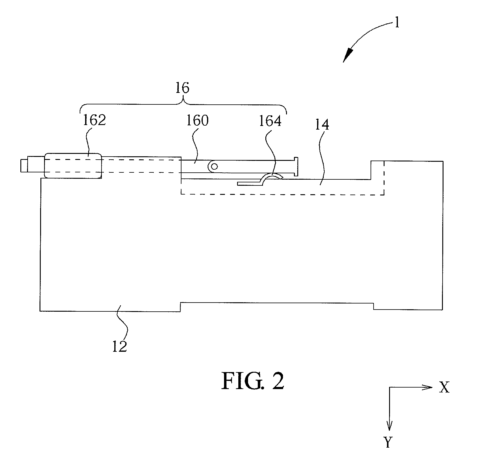
[0027]Compared with the conventional technology, when the antenna body is hidden in the casing of the electronic device, the antenna body contacts with the conducting element to form a loop. At the time, the antenna body and the conducting element are functioned as an IFA. When the antenna body is extended from the casing of the electronic device, the antenna body does not contact with the conducting element. At the time, the antenna body can be functioned as a monopole antenna. Thus, no matter whether the antenna b...


PUM


Abstract

An antenna module includes an antenna body, a signal feeding element and a conducting element. The signal feeding element is mounted on the antenna body, and the antenna body can move between a first position and a second position relative to the signal feeding element. When the antenna body is at the first position, the antenna body contacts and conducts with the conducting element to form a loop. When the antenna body is at the second position, the antenna body does not contact with the conducting element. In an embodiment, antenna receives signal well in both position.

Description

CROSS REFERENCE TO RELATED APPLICATIONS[0001]This Non-provisional application claims priority under 35 U.S.C. §119(a) on Patent Application No(s). 201010266488.4 filed in People's Republic of China on Aug. 30, 2010, the entire contents of which are hereby incorporated by reference.BACKGROUND OF THE INVENTION[0002]1. Field of Invention[0003]The invention relates to an antenna module and, more particularly, to an antenna module applied to an electronic device.[0004]2. Related Art[0005]As mobile devices (such as a notebook computer, a mobile phone, or a personal digital assistant) are widely used, more and more additional functions are needed. One of the additional functions is the digital TV. The digital TV becomes more and more mobilized, so as to provide a diversified and convenient life to users. Consequently, the television broadcast digitalization is developed globally. For example, a DTV tuner of a mini plug-and-play device, such as a portable USB dongle, or a handheld TV integr...

Claims


Application Information

Patent Timeline
Patent Type & Authority Patents(United States)
IPC IPC(8): H01Q1/24H01Q1/10
CPCH01Q1/244
Inventor CHANG, CHIA-HAOHUANG, MIN-JUI
Owner ASUSTEK COMPUTER INC
Learn More