Interlocking test weight system

a technology of interlocking test and weight system, which is applied in the direction of weighing apparatus, weighing apparatus details, containers, etc., can solve the problems of unstable system, inability to use, and impracticality of large test weight assemblies,

Active Publication Date: 2014-11-18
KONECRANES GLOBAL
View PDF26 Cites 0 Cited by
  • Summary
  • Abstract
  • Description
  • Claims
  • Application Information

AI Technical Summary

Problems solved by technology

Test weight assemblies constructed of water bags, concrete blocks, or buckets of scrap metal are impractically large and may be unstable.
Furthermore, those systems may be inappropriate for use in a nuclear utility environment due to difficulties in decontamination and not being rated for seismic activity.

Method used


Image

  • Interlocking test weight system
  • Interlocking test weight system
  • Interlocking test weight system

Examples


Embodiment Construction

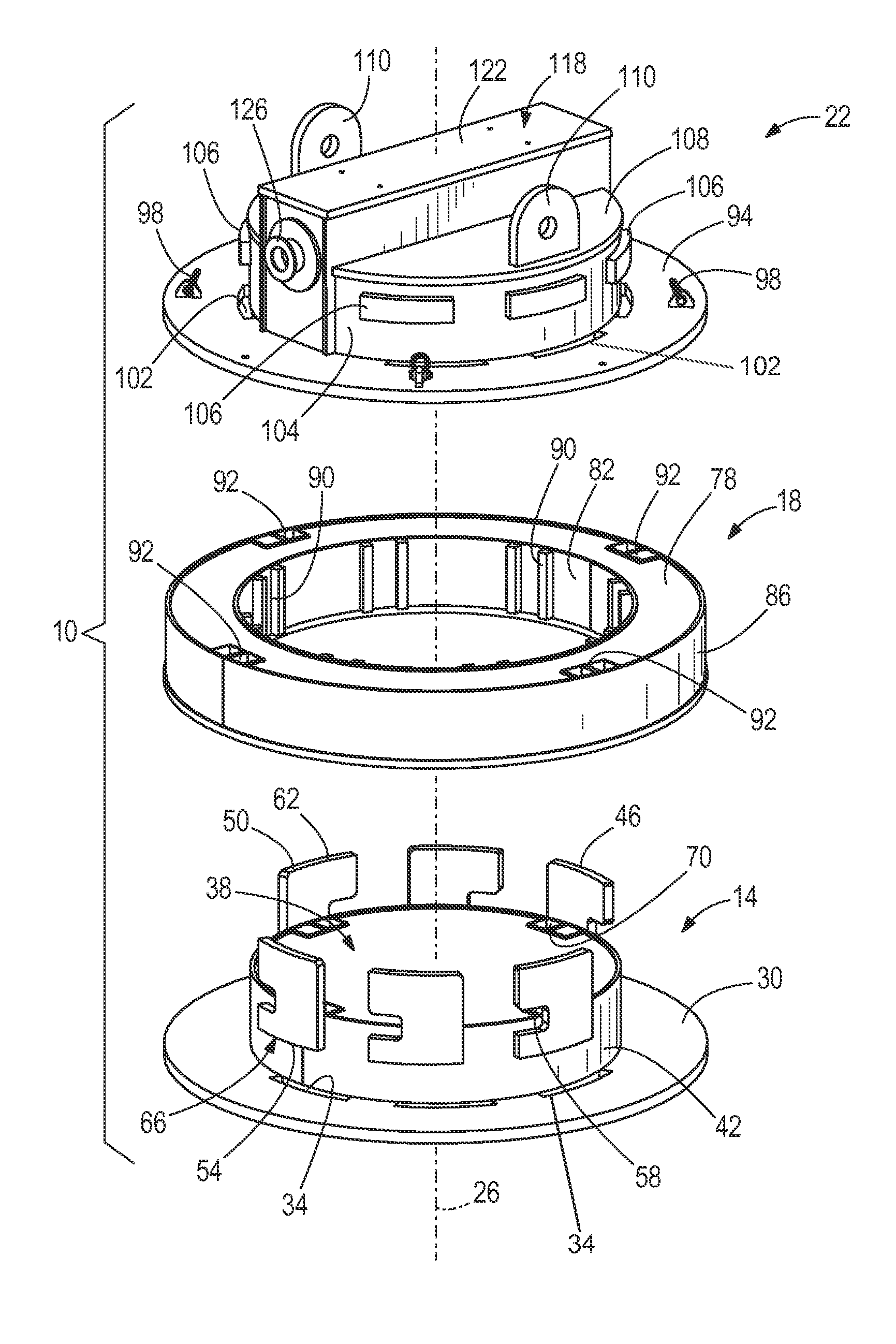
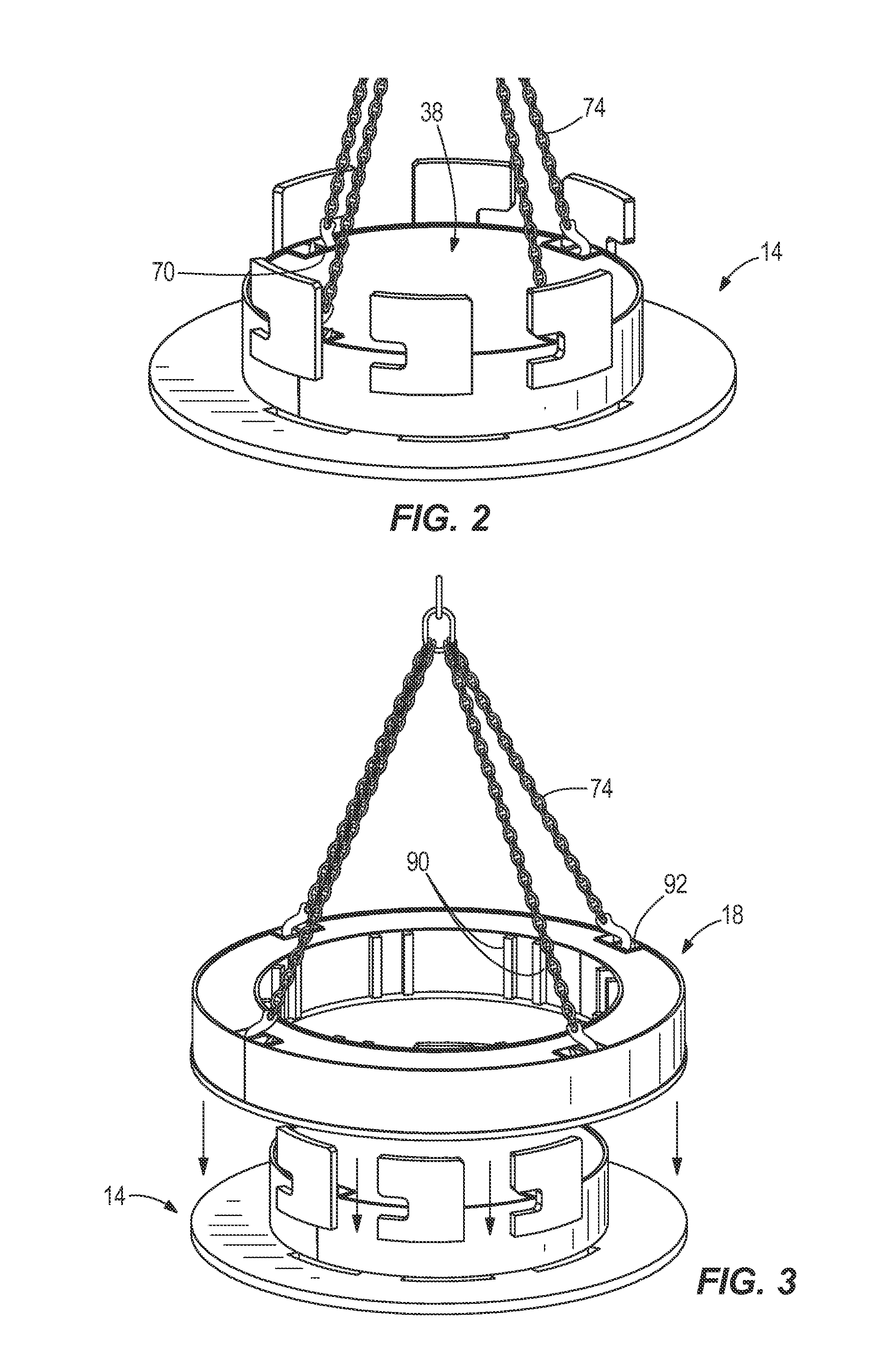
[0022]Referring to FIG. 1, a test weight assembly 10 includes an inner assembly 14, an outer assembly 18, and an upper assembly 22, each oriented along a vertical axis 26. As used herein, a test weight assembly may include any combination of at least one inner assembly 14 and one upper assembly 22.

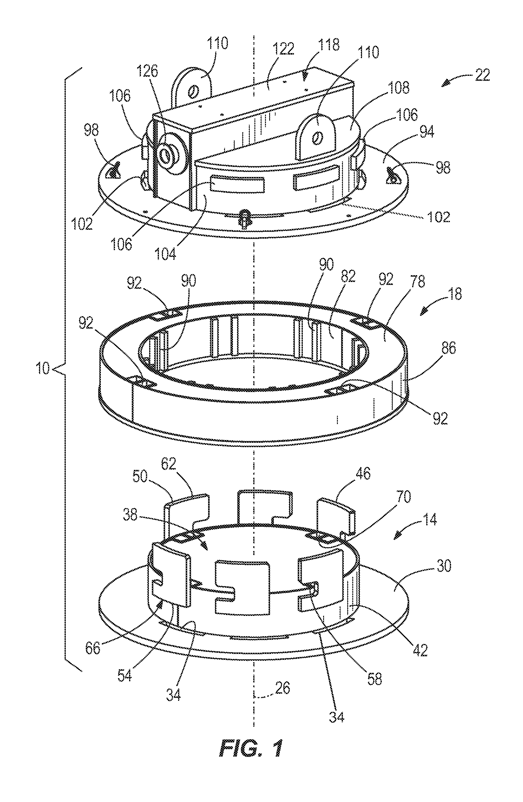
[0023]The inner assembly 14 includes a substantially planar, disc-like bottom plate 30. The bottom plate 30 defines circumferentially arranged slots 34. The slots 34 surround a substantially cylindrical inner body 38 that extends axially from the bottom pate 30. The inner body 38 includes an outer wall 42.

[0024]Ear members 46 are coupled to, and circumferentially arranged about, the outer wall 42. Each ear member 46 includes a top surface 50, a bottom surface 54, and a notch 58 disposed between the top surface 50 and the bottom surface 54. An upper ear portion 62 is defined between the notch 58 and the top surface 50, while a lower ear portion 66 is defined between the notch 58 and the bot...


PUM


Abstract

A test weight system includes a first assembly having a first body member and a plurality of ear members arranged about the first body member. The test weight system also includes a second assembly interlocked with the first assembly, the second assembly having a second body member defining a plurality of slots. A portion of each ear member extends through one of the plurality of slots.

Description

CROSS-REFERENCE TO RELATED APPLICATIONS[0001]This application claims the benefit of U.S. Provisional Patent Application No. 61 / 666,387, filed Jun. 29, 2012, the entire contents of which are incorporated herein by reference.BACKGROUND OF THE INVENTION[0002]The present invention relates to test weight assemblies for the testing and certification of material handling equipment. More specifically, the present invention relates to test weight assemblies for nuclear material handling, such as the handling of spent nuclear fuel casks and reactor components. Test weight assemblies constructed of water bags, concrete blocks, or buckets of scrap metal are impractically large and may be unstable. Furthermore, those systems may be inappropriate for use in a nuclear utility environment due to difficulties in decontamination and not being rated for seismic activity.SUMMARY OF THE INVENTION[0003]In accordance with one construction, a test weight system includes a first assembly having a first body...

Claims


Application Information

Patent Timeline
Patent Type & Authority Patents(United States)
IPC IPC(8): B66C23/74G01G23/01
CPCB66C15/00B66C23/74G01G21/26G01G23/01B65D2590/0058
Inventor YUSTUS, JOSEPH, A.
Owner KONECRANES GLOBAL
Why Eureka
Try Eureka