Multi-function handle for weight training machine

a multi-functional, weight training machine technology, applied in the direction of weights, resilient force resistors, gymnastic exercise, etc., can solve the problems of multi-functional machines, the handle, strap or other component that the exerciser grasps or otherwise contacts, and the movement is more difficul

Inactive Publication Date: 2014-11-25
CORE HEALTH & FITNESS
View PDF13 Cites 10 Cited by
  • Summary
  • Abstract
  • Description
  • Claims
  • Application Information

AI Technical Summary

Problems solved by technology

Conventionally, movement of the mechanical member is resisted in some fashion (often by weights) to render the movement more difficult and thereby intensify the exercise.
One issue that can arise with multi-function machines is the handle, strap or other component that the exerciser grasps or otherwise contacts during exercise.
For example, one style of handle may have a grip that is easily grasped by the hand for an arm or chest exercise, but that would be uncomfortable or unwieldy for use on the foot or ankle.
Of course, the use of multiple handles can render the exercise session more time-consuming due to the need to change out the handles between exercises, and there is an addition inconvenience in having to store and keep track of multiple handles.

Method used


Image

  • Multi-function handle for weight training machine
  • Multi-function handle for weight training machine
  • Multi-function handle for weight training machine

Examples


Embodiment Construction

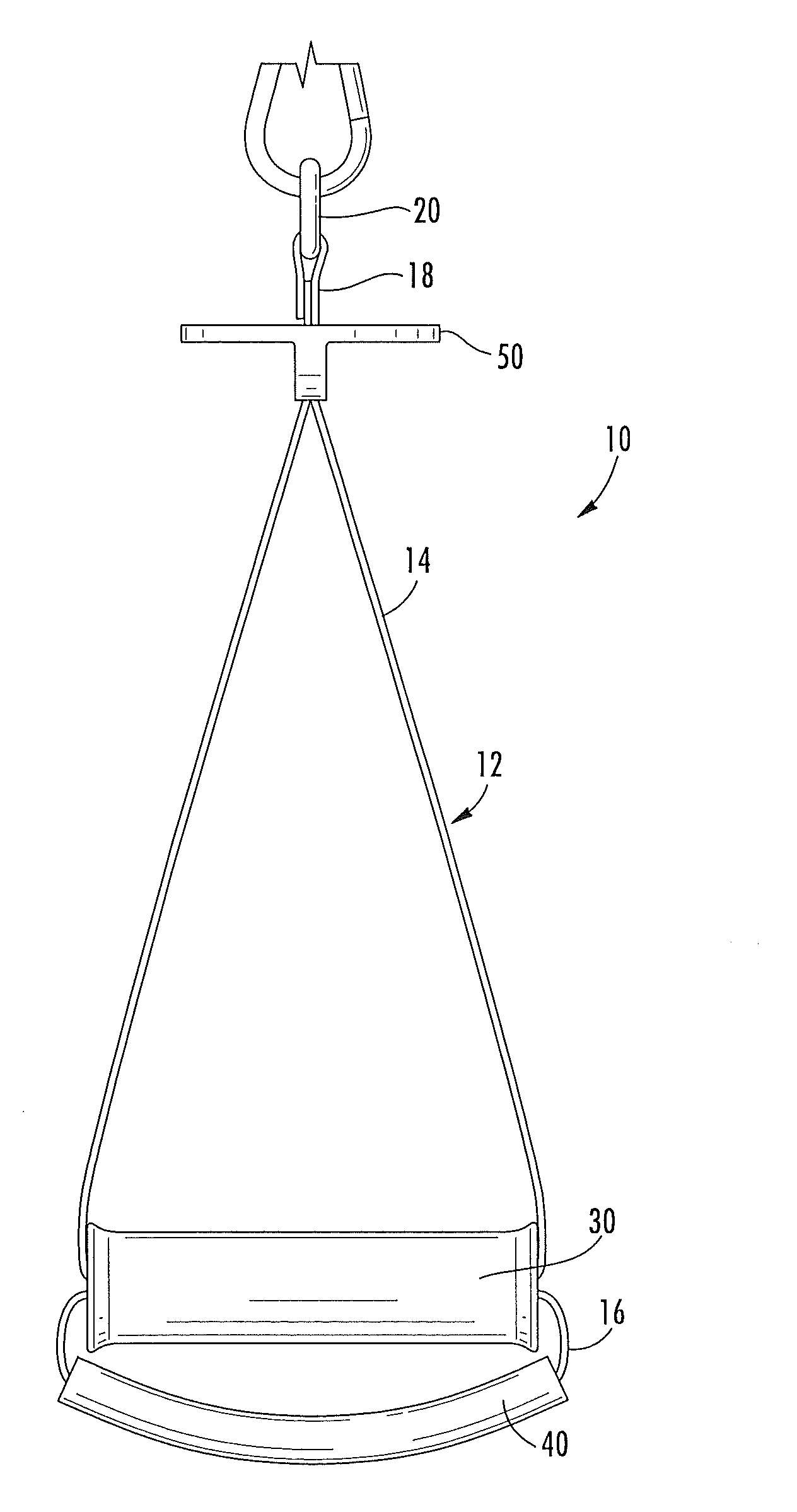
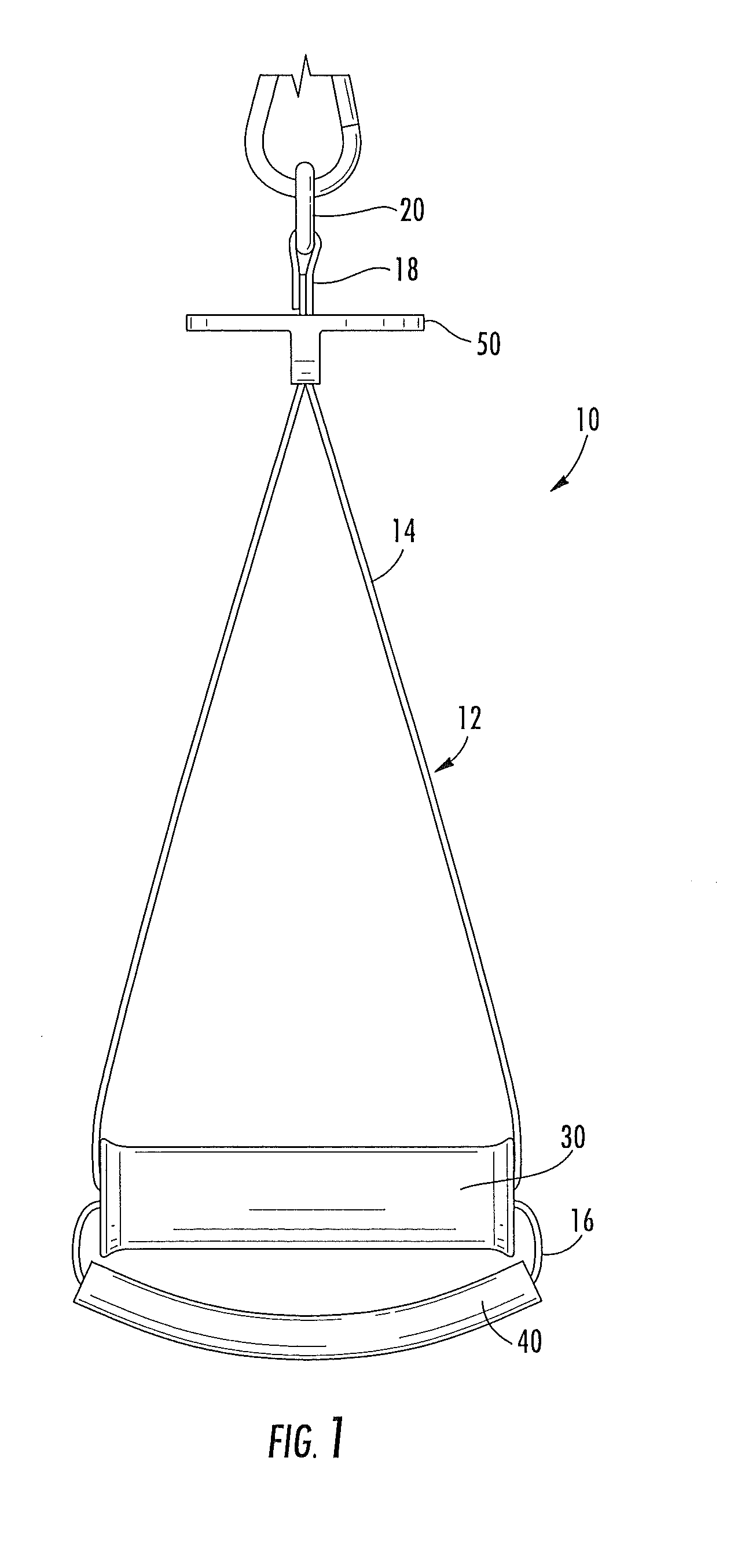
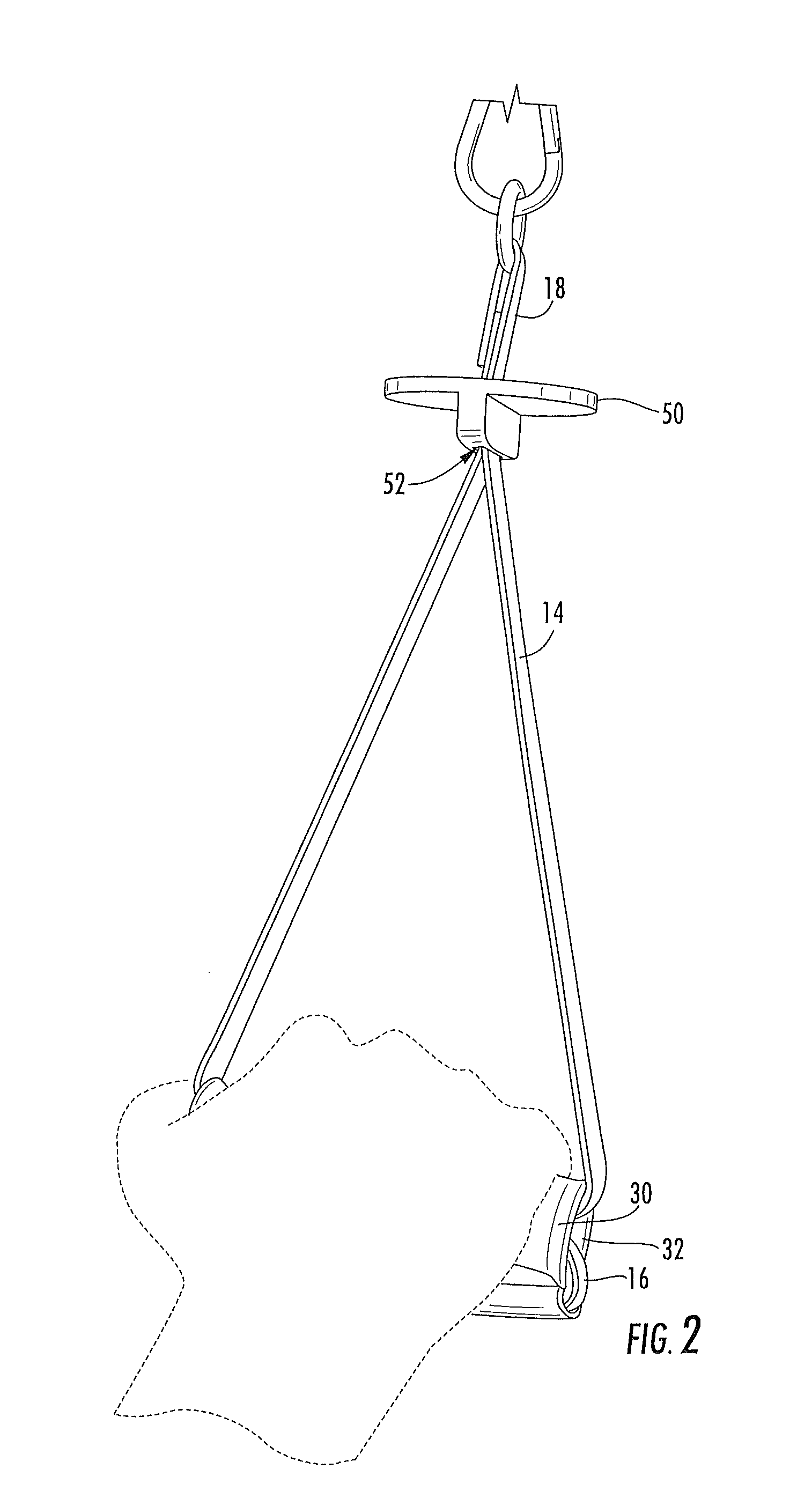
[0019]The present invention will be described more particularly hereinafter with reference to the accompanying drawings. The invention is not intended to be limited to the illustrated embodiments; rather, these embodiments are intended to fully and completely disclose the invention to those skilled in this art. In the drawings, like numbers refer to like elements throughout. Thicknesses and dimensions of some components may be exaggerated for clarity. Well-known functions or constructions may not be described in detail for brevity and / or clarity.

[0020]Unless otherwise defined, all terms (including technical and scientific terms) used herein have the same meaning as commonly understood by one of ordinary skill in the art to which this invention belongs. It will be further understood that terms, such as those defined in commonly used dictionaries, should be interpreted as having a meaning that is consistent with their meaning in the context of the relevant art and will not be interpre...


PUM


Abstract

A multi-functional handle assembly for an exercise machine includes: a strap arranged in a Figure-8 configuration to form a near loop and a far loop extending in generally opposite directions from a crossing point in the strap; a handle having a cavity formed therethrough, wherein the near loop extends to the near side of the handle and the far loop extends from the far side of the handle, the crossing point of the strap positioned in the cavity; a cushioning cuff attached to the far loop; a bearing member having a slot, wherein portions of the near loop are threaded through the slot, such that the bearing member is slidable relative to the portions of the near loop; and means for attaching the handle assembly to the exercise machine, the means for attaching the handle assembly being attached to the near loop. The handle can be drawn between the bearing member and the cushioning cuff, the strap sliding within the handle, such that the near loop and the far loop change in size with sliding of the handle. Movement of the handle and the bearing member can enable the handle assembly to be used with upper body, triceps extension, and leg / hip exercises.

Description

FIELD OF THE INVENTION[0001]The present invention relates generally to exercise equipment, and relates more particularly to weight training equipment.BACKGROUND OF THE INVENTION[0002]Exercise devices, and in particular weight training machines, typically include a mechanical member that the user repeatedly moves along a prescribed path for exercise. Conventionally, movement of the mechanical member is resisted in some fashion (often by weights) to render the movement more difficult and thereby intensify the exercise. The movement of the mechanical member determines what muscle or muscle groups are to be involved in the exercise.[0003]One exercise device that has become prevalent in recent years is the multi-functional exercise machine, which enables the user to position components of the machine in different locations in order to perform different exercises. These machines have proven to be particularly popular for serious exercisers and for exercisers that work with personal traine...

Claims


Application Information

Patent Timeline
Patent Type & Authority Patents(United States)
IPC IPC(8): A63B21/072A63B21/078A63B21/02A63B21/00A63B21/075A63B23/12A63B21/062A63B71/00
CPCA63B21/062A63B21/075A63B21/1469A63B21/078A63B23/12A63B21/072A63B21/0628A63B21/4035A63B23/1209A63B23/03533A63B23/0355A63B21/4043
Inventor WEBB, GREGORY, M.
Owner CORE HEALTH & FITNESS
Why Eureka
Try Eureka