Support structure

a technology of supporting structure and support rod, which is applied in the direction of machine support, furniture parts, rod connections, etc., can solve the problems of fatiguing the user's hand holding an electronic device for a long time, and many electronic devices do not have self-support structures

Active Publication Date: 2014-12-02
FU TAI HUA IND SHENZHEN +1
View PDF18 Cites 14 Cited by
  • Summary
  • Abstract
  • Description
  • Claims
  • Application Information

AI Technical Summary

Problems solved by technology

Many electronic devices do not have self-support structures; and need to be held by hand.
However, it is fatiguing for a user to hold an electronic device by hand for a long time when watching a film for example.

Method used


Image

  • Support structure
  • Support structure
  • Support structure

Examples


Embodiment Construction

[0014]The disclosure is illustrated by way of example and not by way of limitation in the figures of the accompanying drawings in which like references indicate similar elements. It should be noted that references to “an” or “one” embodiment in this disclosure are not necessarily to the same embodiment, and such references mean at least one.

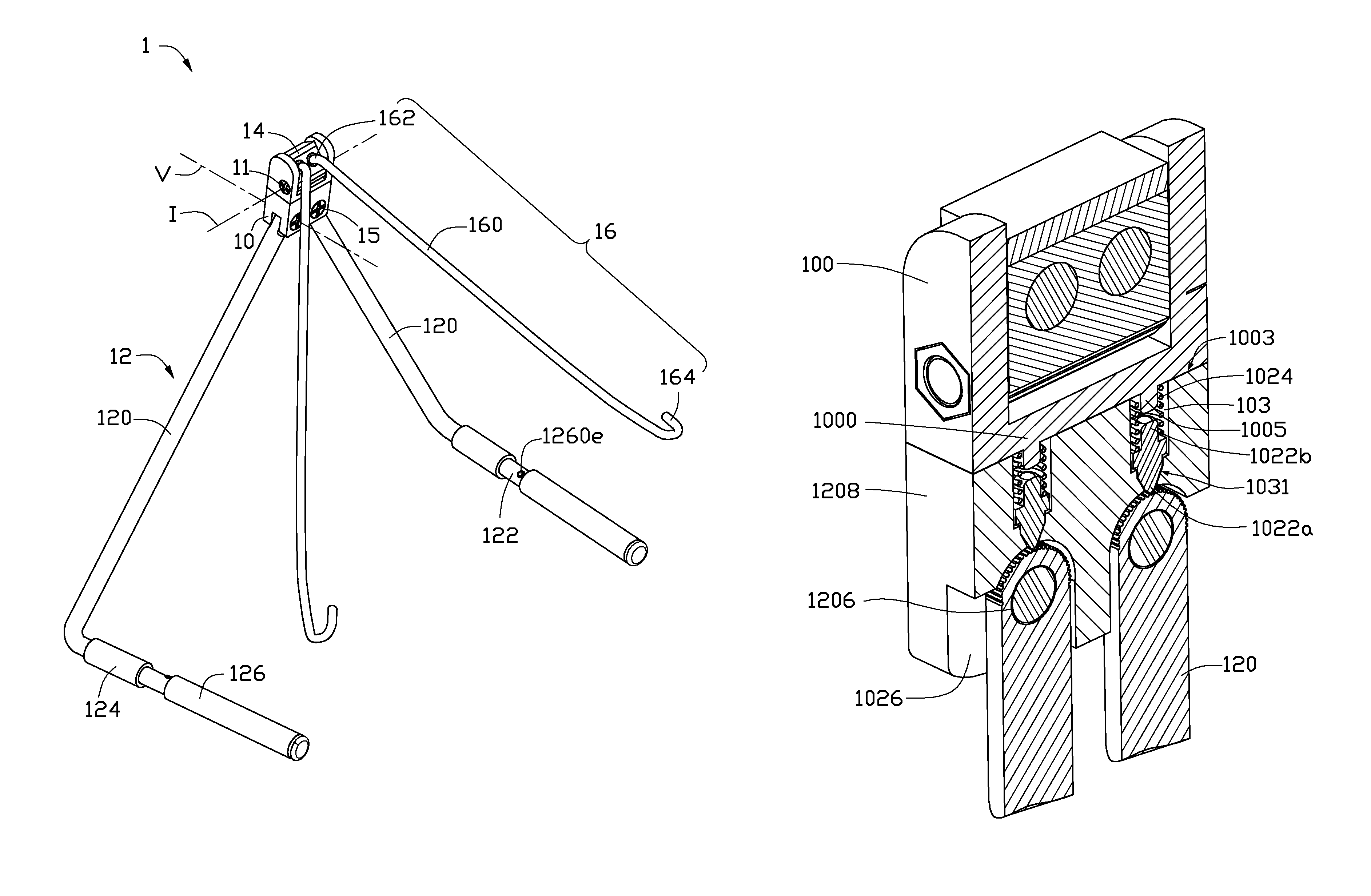
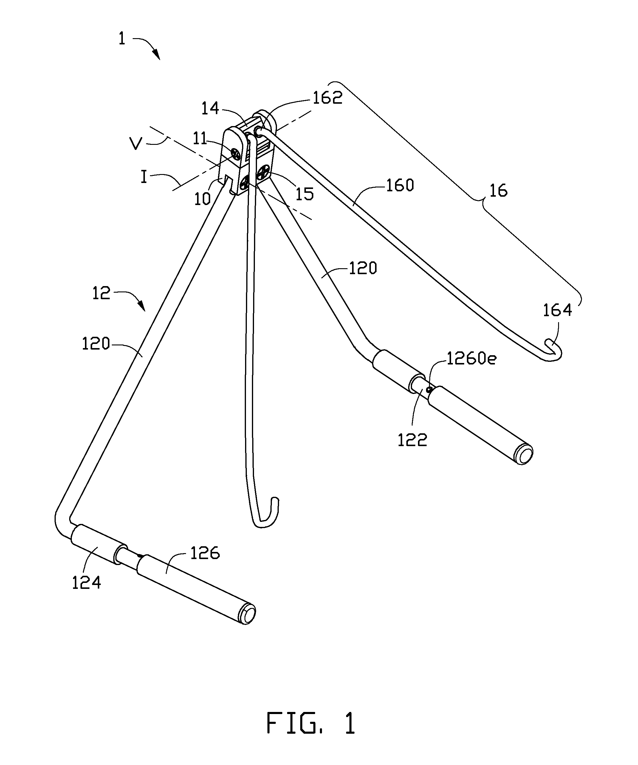
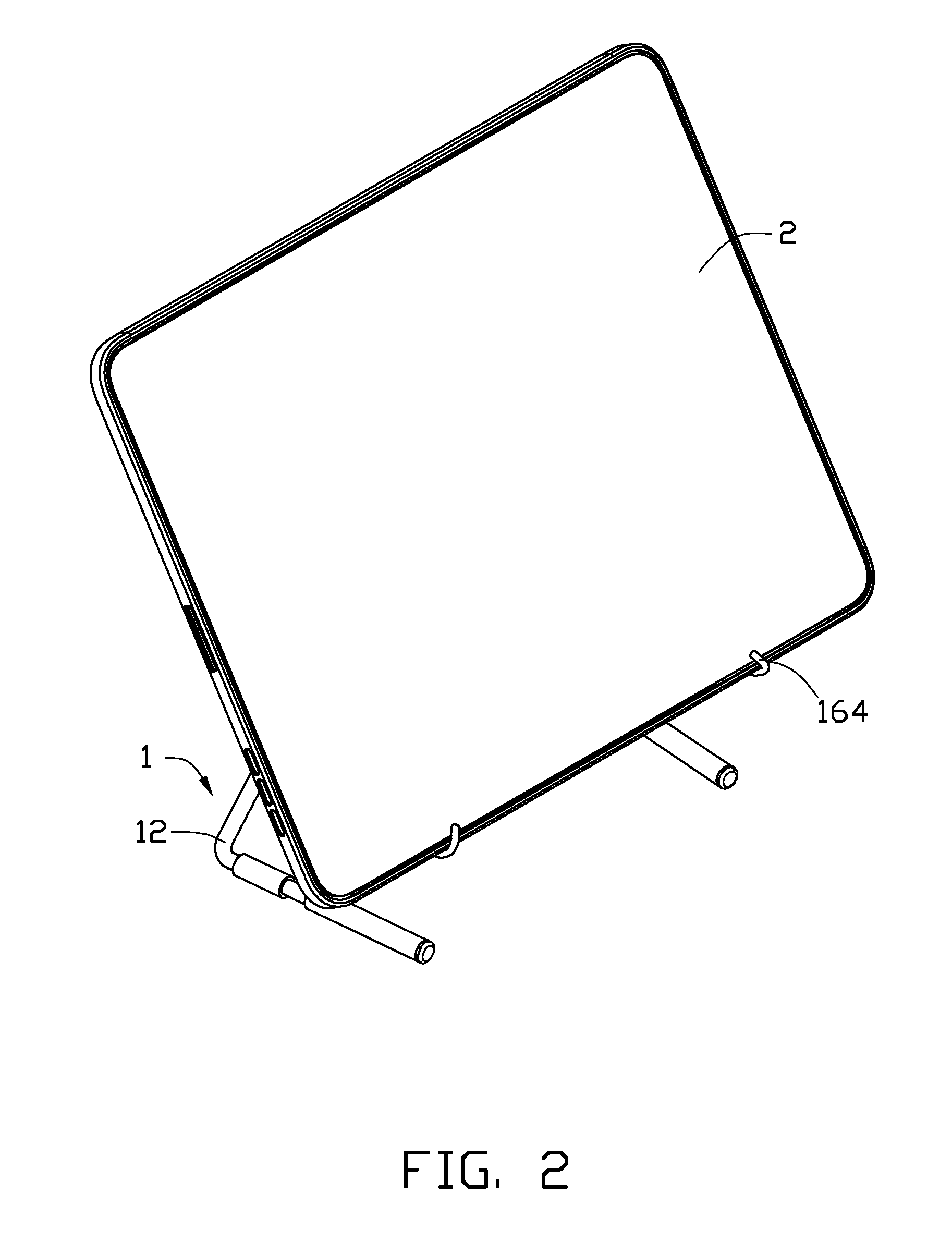
[0015]Refering to FIGS. 1 and 2, in one embodiment, a support structure 1 includes a base 10, a pair of stands 12, a top hinge 14, and a pair of holding arms 16. The stands 12 are rotatably connected to one side of the base 10 to support the base 10. The top hinge 14 is rotatably connected to the other side of the base 10. The rotation axis I of the top hinge 14 is perpendicular to the rotation axis V of the stands 12. The holding arms 16 are for holding an object and are rotatably connected to a side surface of the top hinge 14. In this embodiment, the stands 12 are connected to opposite ends of the side of the top hinge 14. The pair of holding ...


PUM


Abstract

A support structure includes a base, a pair of stands, a top hinge, and a pair of holding arms. The stands are rotatably connected to one end of the base to support the base. The top hinge is rotatably connected to the other end of the base opposite to the stands. The rotation plane of the top hinge is perpendicular to the rotation plane of the stands. The holding arms are rotatably connected to the top hinge for holding an object at any desired angle.

Description

TECHNICAL FIELD[0001]The disclosure generally relates to support structures, and particularly, to a support structure for supporting an electronic device.DESCRIPTION OF RELATED ART[0002]Many electronic devices do not have self-support structures; and need to be held by hand. However, it is fatiguing for a user to hold an electronic device by hand for a long time when watching a film for example.[0003]Therefore, it is desirable to provide a support structure which can overcome the above-mentioned problems.BRIEF DESCRIPTION OF THE DRAWINGS[0004]Many aspects of the disclosure can be better understood with reference to the following drawings. The components in the drawings are not necessarily drawn to scale, the emphasis instead being placed upon clearly illustrating the principles of the disclosure. Moreover, in the drawings, like reference numerals designate corresponding portions throughout the several views.[0005]FIG. 1 is an isometric view of a support structure in accordance with ...

Claims


Application Information

Patent Timeline
Patent Type & Authority Patents(United States)
IPC IPC(8): A47B23/04
CPCF16M11/10F16M2200/024A47B23/043F16B7/18F16M2200/08F16M11/38A47B2023/045F16M13/00
Inventor LIANG, YONGPAN, LIN-LINYU, CHIA-TELU, LIANG-YI
Owner FU TAI HUA IND SHENZHEN
Why Eureka
Try Eureka