Method of manufacturing an optical fibre, preform and optical fibre

a manufacturing method and technology of optical fibre, applied in the field of manufacturing optical fibre, can solve the problems of undesirable oh groups in the external surface of the support tube, group problems in regard to optical properties, and said oh groups produce adverse effects on the light conducting part of the optical fibre, and achieve the effect of negative effect on the deposition efficiency of dopants

Active Publication Date: 2014-12-09
DRAKA COMTEQ BV
View PDF16 Cites 0 Cited by
  • Summary
  • Abstract
  • Description
  • Claims
  • Application Information

AI Technical Summary

Benefits of technology

[0031]One or more of the above objects are accomplished by using such a feature. The present inventors have thus found that the attenuation at a wavelength of 1385 nm in silica fibres can be reduced by using different sledge-velocity from gas- or supply-side to discharge or pump-side and pump-side to gas-side. The reaction zone is preferably a plasma and the resonator generating microwaves is movable over the length of the hollow quartz glass substrate tube.
[0036]The present inventors assume that the beginning position of the plasma is directly influenced by the direction of the movement of the reaction zone travelling along the length of the substrate tube. The present inventors assume that there is a longer plasma tail at the gas-side when moving the reaction zone from gas-side to pump-side. This phenomenon is caused by the fact that the plasma is already ionised in the gas-side region. In a situation in which the reaction zone moves further towards the pump-side, the gas-side plasma tail is easily sustained by the microwaves. On the other hand, when the reaction zone moves towards to the gas-side, the gas-side tail is short, in which the gas-side plasma front is pulled back close to, or even inside, the reaction zone. The present inventors assume that such a longer plasma tail at the gas side will have an influence on the intensity of the position where the deposition of the glass layer inside the substrate tube starts. And the present inventors assume that the intensity of the plasma front has a direct influence on the incorporation of the (O)H molecules in the quartz substrate tube. And such an incorporation of the (O)H molecules in the quartz substrate tube should be kept to a minimum.

Problems solved by technology

High temperatures may lead to the inclusion of the undesirable OH groups in the external surface of the support tube.
Since the support tube forms part of the fibre yet to be drawn, it is to be expected that said included OH groups will present problems as regards the optical properties of the glass fibre that is eventually obtained.
It has become apparent that said OH groups produce adverse effects in the light conducting part of the optical fibre.
Moreover, said absorption peak at 1385 nm limits the use of the fibre over a large wavelength range that recent developments require.

Method used


Image

  • Method of manufacturing an optical fibre, preform and optical fibre
  • Method of manufacturing an optical fibre, preform and optical fibre
  • Method of manufacturing an optical fibre, preform and optical fibre

Examples


Embodiment Construction

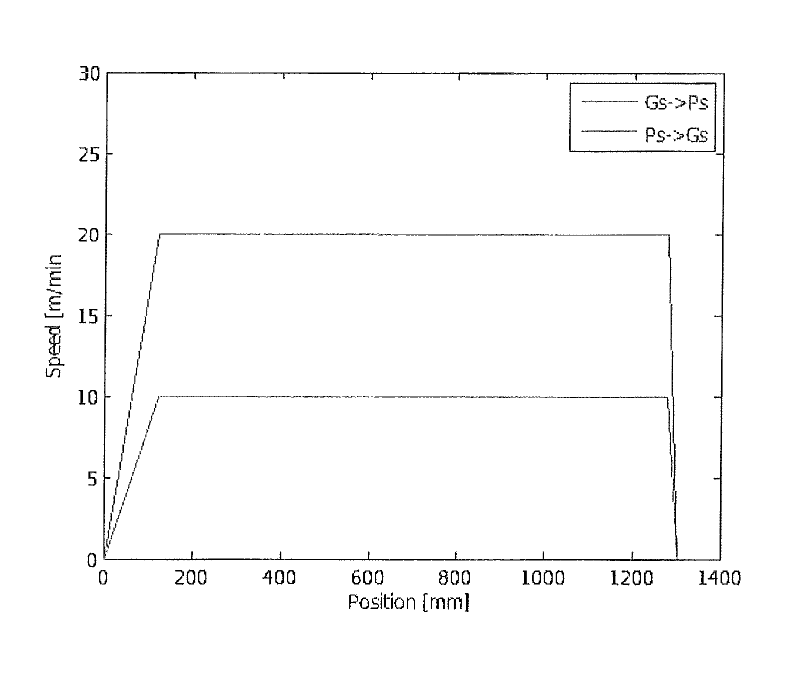
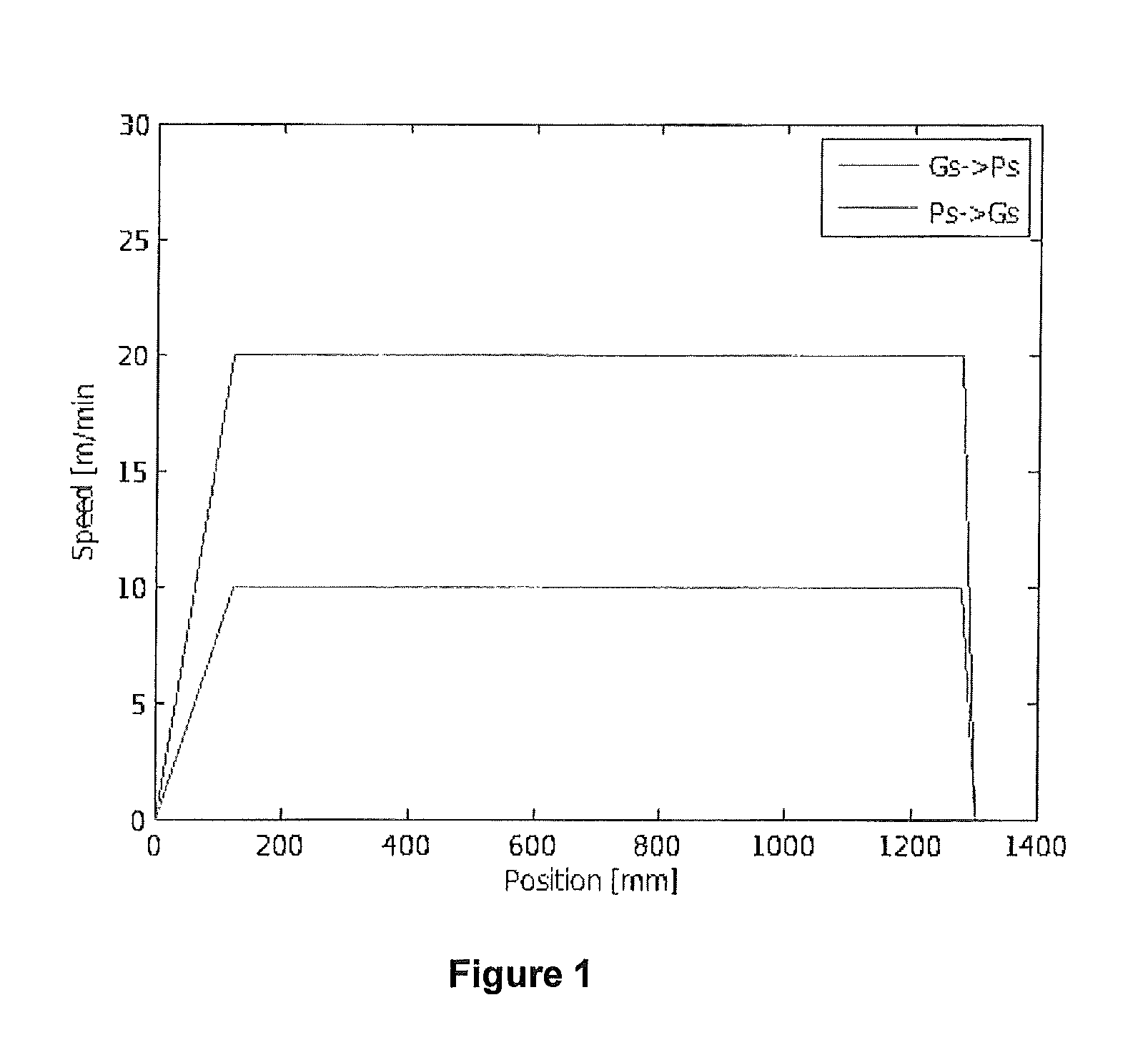
[0049]Using the PCVD technique a preform was produced. As shown in FIG. 1, the velocity profile of the reaction zone over the length of the supply side-to-discharge side is higher than the velocity of the reaction zone over the length of the discharge side-to-supply side. The substrate tube was surrounded by an oven and the reaction zone traveled over the length of substrate tube during the deposition process. The power of the reaction zone, i.e. microwave power, was 7000 Watt. The pressure inside the hollow substrate tube was approximately 14 mbar. The temperature of the oven was set between 1070 and 960 degrees Celsius. The composition of the gaseous components flowing in the hollow substrate tube was about ⅔ parts oxygen, 4 / 6 parts SiCl4 and between 0 and ⅙ parts GeCl4. The deposition process took about 620 minutes. In fact, according to the embodiment disclosed in FIG. 1, the velocity of the reaction zone from gas-side to pump-side was set at a constant value of 20 m / min, wherea...


PUM

PropertyMeasurementUnit
velocityaaaaaaaaaa
velocityaaaaaaaaaa
transmission wavelengthsaaaaaaaaaa

Abstract

A method for manufacturing an optical preform via an internal vapor deposition process, wherein during the inside deposition process the velocity of the reaction zone is set so that the velocity of the reaction zone over the length of the supply side-to-discharge side is higher than the velocity of the reaction zone over the length of the discharge side-to-supply side.

Description

CROSS-REFERENCE TO RELATED APPLICATION[0001]This application claims priority to Dutch Patent Application No. 2006472 filed Mar. 25, 2011, the contents of which are incorporated by reference herein.TECHNICAL FIELD AND BACKGROUND OF THE INVENTION[0002]The present invention relates to a method of manufacturing an optical fibre including the following steps:[0003]i) providing a hollow substrate tube,[0004]ii) passing doped or undoped reactive, glass-forming gases through the interior of the hollow substrate tube,[0005]iii) creating such conditions in the interior of the hollow substrate tube that deposition of glass layers onto the interior of the hollow substrate tube takes place, wherein a non-isothermal plasma is reciprocated between two reversal points along the substrate tube, wherein the velocity of movement of the plasma decreases to zero from each deceleration point to each reversal point,[0006]iv) subjecting the substrate tube thus obtained to a collapsing treatment so as to fo...

Claims


Application Information

Patent Timeline
Patent Type & Authority Patents(United States)
IPC IPC(8): C03B37/018
CPCC03B37/01823C03B37/01815C03B37/0183C03B2201/31
Inventor MILICEVIC, IGORVAN STRALEN, MATTHEUS JACOBUS NICOLAASHARTSUIKER, JOHANNES ANTOONALDEA, EUGENKUIJPERS, ERIC ALOYSIUS
Owner DRAKA COMTEQ BV
Why Eureka
Try Eureka