
Multi-view display apparatus

a multi-view display and display device technology, applied in the field of display devices, can solve the problems of low resolution of 3d display, high cost and bulky 3d display, and high cost of 3d display, and achieve the effect of reducing the number of actual illuminators, easy maintenance, and less cos

Active Publication Date: 2015-05-26
DELTA ELECTRONICS INC
View PDF13 Cites 1 Cited by
  • Summary
  • Abstract
  • Description
  • Claims
  • Application Information

AI Technical Summary

Benefits of technology

[0021]2. The light sources are shared by the two spatial light modulators, so as to decrease the number of actual illuminators; and
[0022]3. More view zones can be more easily sustained than is currently feasible with a lenticular or parallax barrier display, and a large number of views can be supported less expensively than with multi-projector. The challenge of time-multiplex method in producing light modulators with sufficiently fast refresh rates is much decreased.

Problems solved by technology

Alioscopy and NewSight each provide a cheaper 3D display with small volume for naked eye viewing, but this 3D display has a low-resolution.
Holografika provides a 3D display having a high-resolution for naked eye viewing, but this 3D display is expensive and bulky.
Holografika's 3D display uses many projectors, and therefore this 3D display is expensive and bulky.
In view of the foregoing, there exist problems and disadvantages in the current 3D multi-view display techniques that await further improvement.
However, those skilled in the art sought vainly for a solution.
1. No light is wasted when two spatial light modulators are combined with the combining prism;
2. The light sources are shared by the two spatial light modulators, so as to decrease the number of actual illuminators; and
3. More view zones can be more easily sustained than is currently feasible with a lenticular or parallax barrier display, and a large number of views can be supported less expensively than with multi-projector. The challenge of time-multiplex method in producing light modulators with sufficiently fast refresh rates is much decreased.

Method used


Image

  • Multi-view display apparatus
  • Multi-view display apparatus
  • Multi-view display apparatus

Examples


Embodiment Construction

[0033]In the following detailed description, for purposes of explanation, numerous specific details are set forth in order to attain a thorough understanding of the disclosed embodiments. It will be apparent, however, that one or more embodiments may be practiced without these specific details.

[0034]In other instances, well-known structures and devices are schematically shown in order to simplify the drawing.

[0035]As used in the description herein and throughout the claims that follow, the meaning of “a”, “an”, and “the” includes reference to the plural unless the context clearly dictates otherwise. Also, as used in the description herein and throughout the claims that follow, the terms “comprise or comprising”, “include. or including”, “have or having”, “contain or containing” and the like are to be understood to be open-ended, i.e., to mean including but not limited to. As used in the description herein and throughout the claims that follow, the meaning of “in” includes “in” and “...


PUM


Abstract

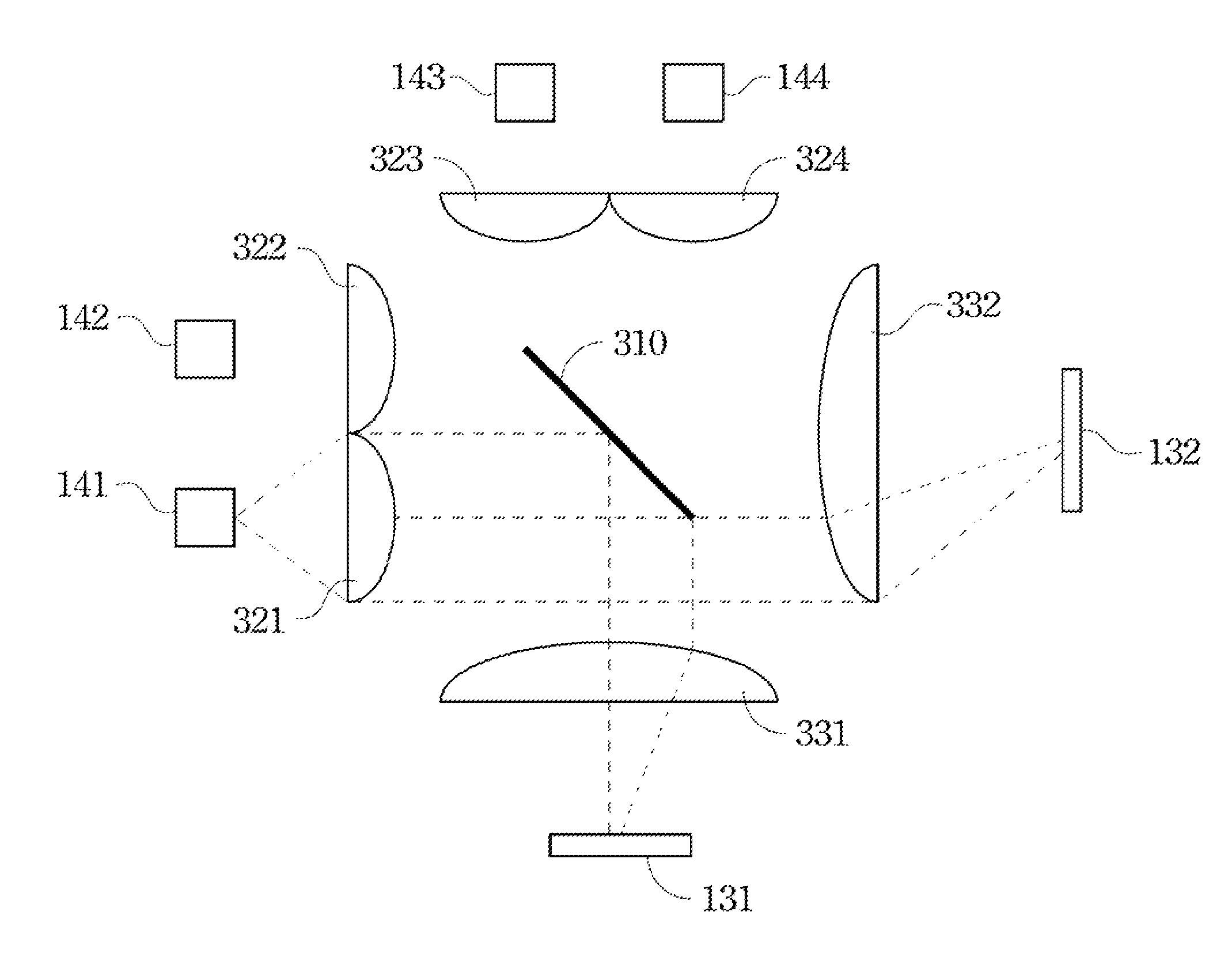
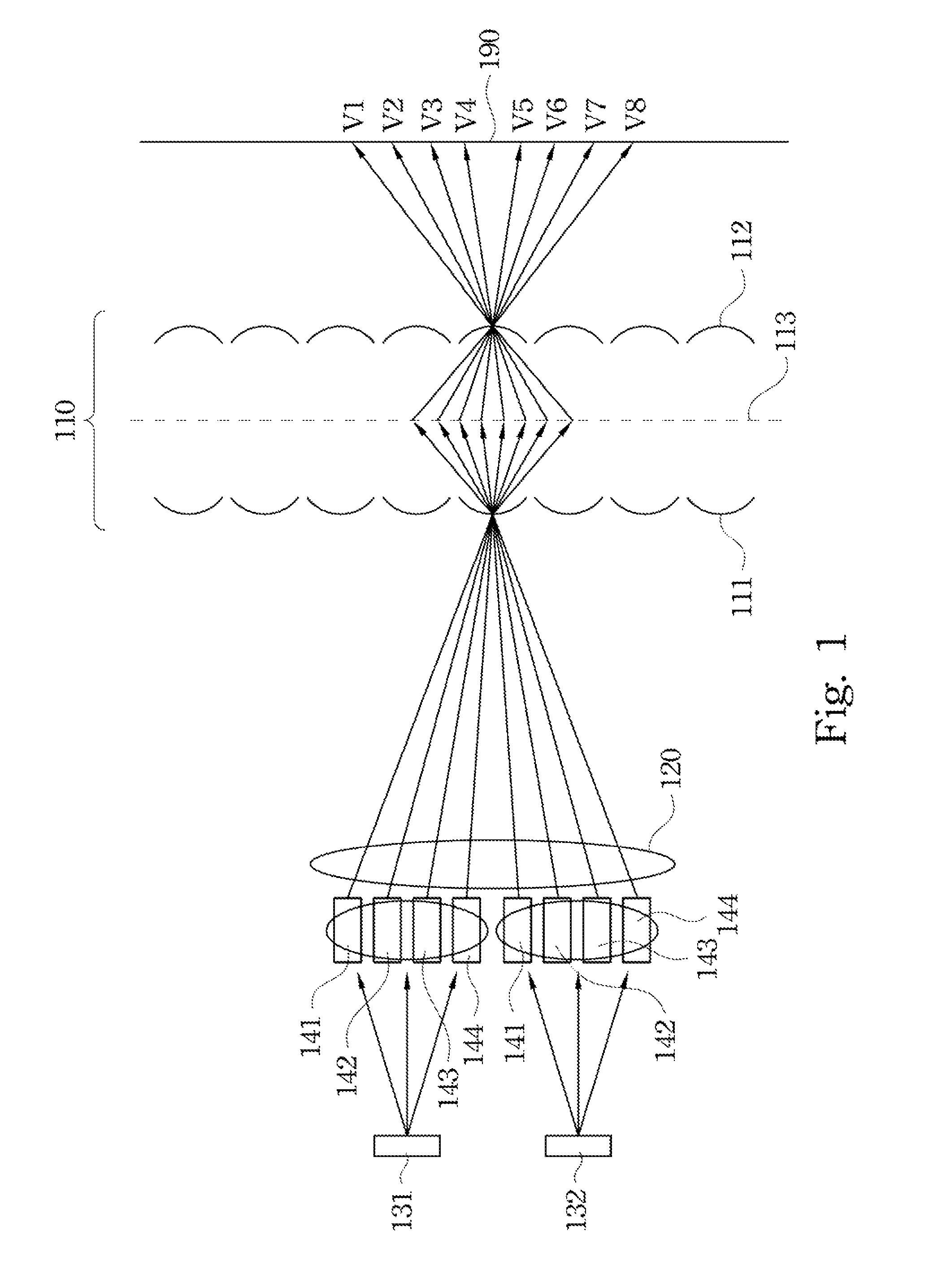
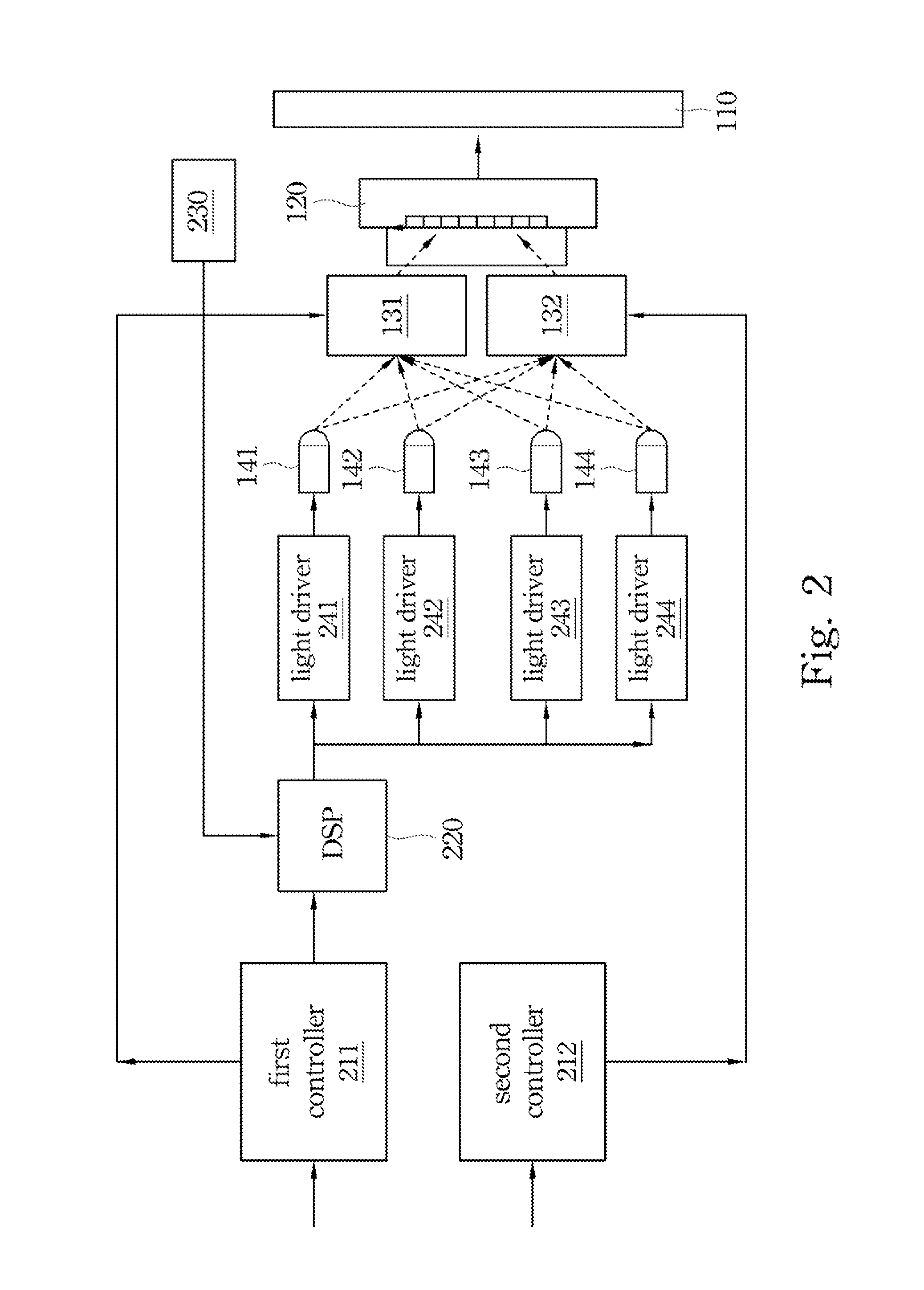
A multi-view display apparatus includes a screen, a projection lens, two spatial light modulators, light sources, an optical guidance system and a combining prism. The light sources can radiate light in turn. When one of the light sources radiate light, the optical guiding system can divide the light into two portions and guide the two portions of the light to the spatial light modulators respectively, and the spatial light modulators can reflect the light. The combining prism can transmit light that is reflected from the spatial light modulators to the projection lens, where the projection lens is aligned with the screen in an optical path so that the screen can receive the light that is projected from the projection lens.

Description

RELATED APPLICATIONS[0001]This application claims priority to Taiwan Application Serial Number 100145463, filed Dec. 9, 2011, which is herein incorporated by reference.BACKGROUND[0002]1. Technical Field[0003]The present disclosure relates to display devices, and more particularly, o multi-view display apparatus.[0004]2. Description of Related Art[0005]Providing vivid images to the consumers has long been the goal of display manufacturers and researchers. Among various advanced techniques, is the application of three-dimensional (3D) stereoscopy is one of the most sought after fields.[0006]The 3D multi-view display technology has been developed by numerous manufacturers, such as Alioscopy, Apple, the Dimension Technologies, the Fraunhofer the HHI Holografika, a, i-Art, NewSight, Philips, SeeFront, SeeReal Technologies, Spatial, View, Tridelity, Sharp, Epson, Bolod, Spatial, View, StereoGraphics, 3D Experience Ltd, Opticality, Miracube, ACT Kern, Dresden 3D GmbH, LightSpace Technologi...

Claims


Application Information

Patent Timeline
Patent Type & Authority Patents(United States)
IPC IPC(8): G02B27/14G03B21/26G03B21/20G03B21/602H04N13/04
CPCG03B21/2013G03B21/2033G03B21/2066G03B21/602H04N13/0418H04N13/045H04N13/0459H04N13/32H04N13/354H04N13/363
Inventor HUANG, JUNE-JEI
Owner DELTA ELECTRONICS INC
Learn More