
Holding arm apparatus for medical tool

a technology of holding arm and holding arm, which is applied in the direction of mechanical control devices, instruments, applications, etc., can solve the problem that the holding arm of the related art, however, achieves a small rotation angle, and achieves the effect of small rotation angl

Inactive Publication Date: 2014-12-16
MITAKA KOHKI
View PDF17 Cites 3 Cited by
  • Summary
  • Abstract
  • Description
  • Claims
  • Application Information

AI Technical Summary

Problems solved by technology

The arm of the related art, however, achieves a small rotation angle because the parallel linkage that supports the arm is unable to widely change the position or angle of the medical tool.

Method used


Image

  • Holding arm apparatus for medical tool
  • Holding arm apparatus for medical tool
  • Holding arm apparatus for medical tool

Examples


Embodiment Construction

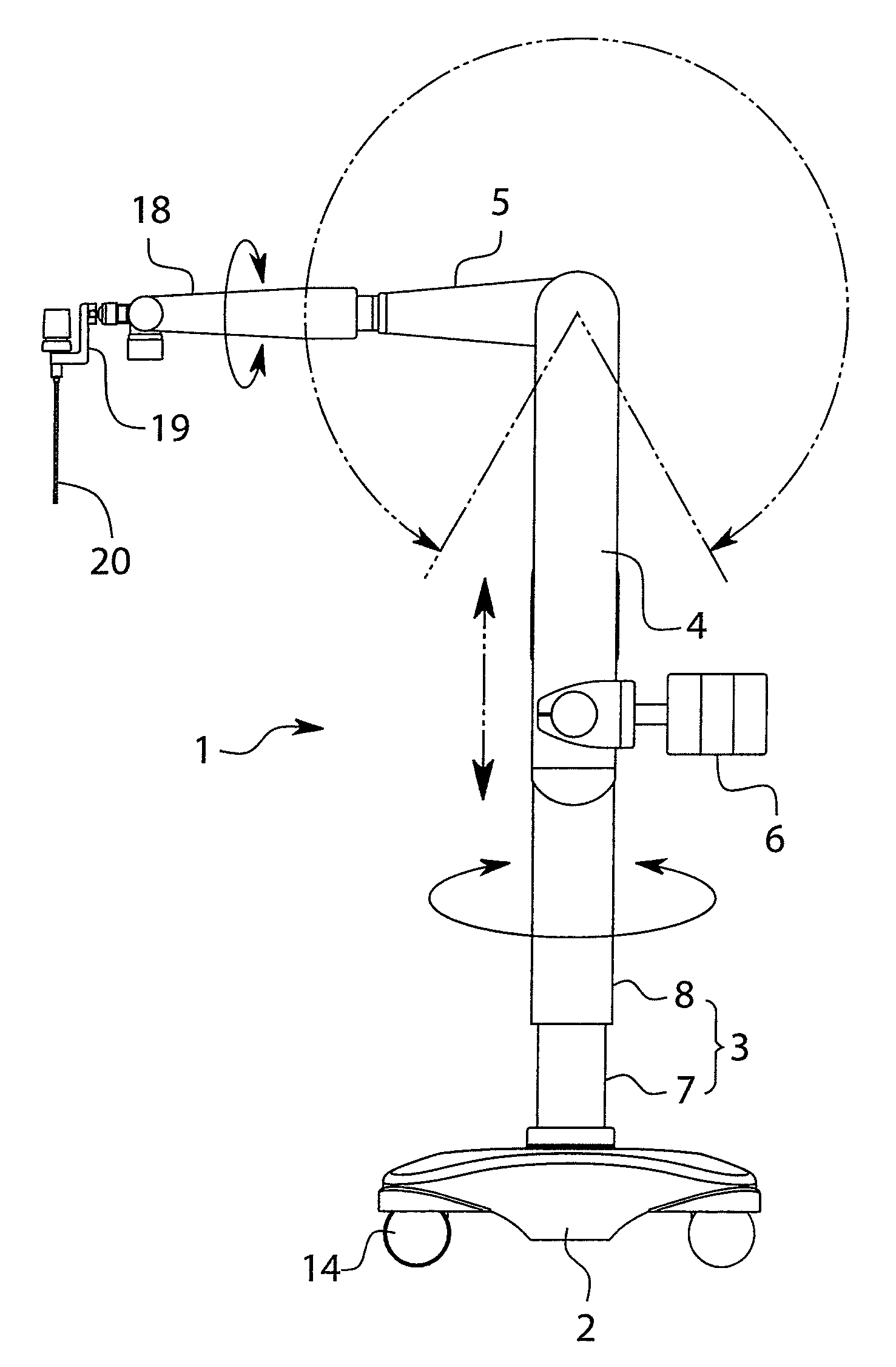
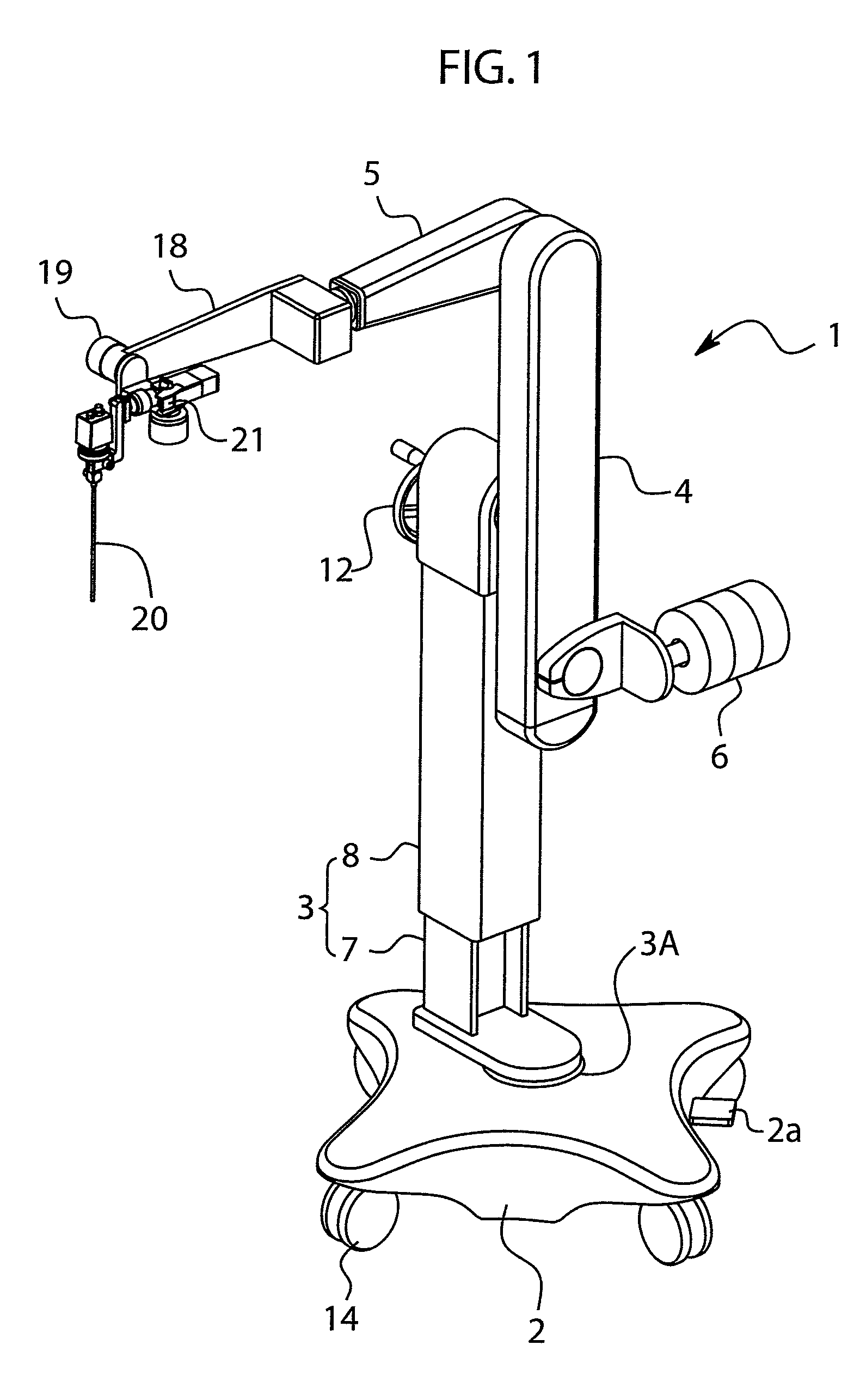
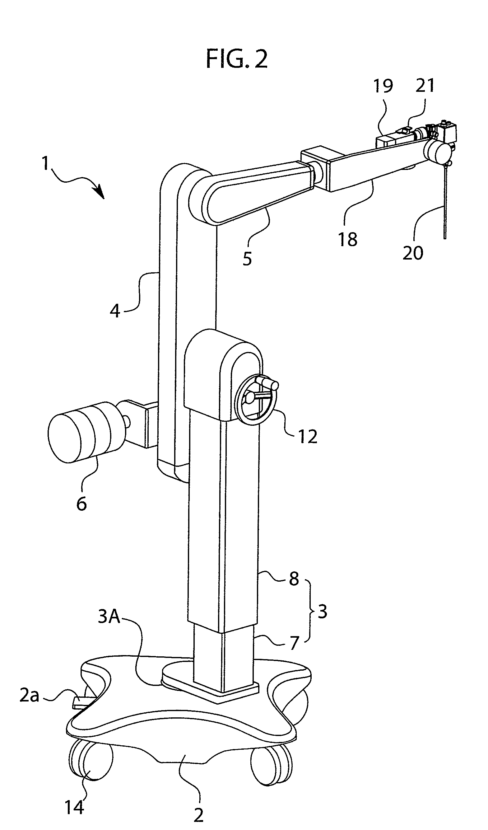
[0019]A preferred embodiment of the present invention will be explained with reference to the drawings. A holding arm apparatus 1 according to the present embodiment includes a base unit 2, a support unit 3, a vertical arm unit 4, a horizontal arm unit 5, and a counterweight 6.

[0020]The base unit 2 has casters 14 at four corners to move along a floor and a foot-type brake mechanism 2a to fix the casters 14 in a position to the floor.

[0021]The support unit 3 is upright at a position shifted from a rotary shaft 3A that is at the center of the base unit 2. The support unit 3 is horizontally rotatable around the rotary shaft 3A. The rotary shaft 3A has a clutch (not illustrated) to immobilize the rotary shaft 3A. The clutch according to the embodiment is an air-type clutch driven by compressed air. It may be an electromagnetic clutch.

[0022]The support unit 3 has a stationary support 7 rotatably fixed to the base unit 2 and a movable support 8 vertically slidable along the stationary sup...


PUM


Abstract

A holding arm apparatus 1 is configured to connect upper and lower timing pulleys 5A and 6A of a vertical arm unit 4 to each other with a timing belt 15, to widen the range of rotation angle of a horizontal arm unit 5 and allow the position and angle of an endoscope 20 held at a front end of the horizontal arm unit 5 to be widely changed. The horizontal arm unit 5 and a counterweight 6 turn by the same angle, to maintain a weight balance by the counterweight 6. Using the timing belt 15 reduces the total weight and operation noise of the holding arm apparatus 1. Accordingly, the apparatus is appropriate for a medical front.

Description

TECHNICAL FIELD[0001]The present invention relates to a holding arm apparatus for medical tool.BACKGROUND TECHNOLOGY[0002]In a medical field, various tools are used in recent years. For example, endoscopes, ultrasonic echo probes, brain retractors, aspiration tubes, and other kinds of tools are used. Such a medical tool must be held for a patient at a proper position. For this, a holding arm apparatus using a parallel linkage is employed.[0003]The holding arm apparatus of this type holds a medical tool at an end of an arm of the parallel linkage (including a belt driving mechanism) and has a counterweight at the other end of the arm. For example, Japanese Unexamined Patent Application Publications No. 2002-165804 and No. 2005-211667 disclose apparatuses capable of maintaining a weight balance with respect to a medical tool, setting the medical tool at a required position and angle, and fixing the state with clutches.SUMMARY OF INVENTION[0004]The arm of the related art, however, achi...

Claims


Application Information

Patent Timeline
Patent Type & Authority Patents(United States)
IPC IPC(8): B25J18/04A61B19/00
CPCA61B2019/266Y10S901/21A61B19/26A61B2019/263Y10T74/20323Y10T74/20305A61B90/50A61B2090/5025A61B2090/508
Inventor NAKAMURA, KATSUSHIGEDOI, MASAOHASHIMOTO, TATSUYANAKAMURA, MASAKAZU
Owner MITAKA KOHKI
Learn More