Force measurement system

a technology of force measurement and force, applied in the field of force measurement systems, can solve the problems of increasing the difficulty of transporting, requiring additional hardware for carrying two separate plates, and requiring significant weight of the system

Active Publication Date: 2014-12-23
BERTEC
View PDF32 Cites 65 Cited by
  • Summary
  • Abstract
  • Description
  • Claims
  • Application Information

AI Technical Summary

Problems solved by technology

However, using two separate plates requires carrying additional hardware.
When two plates are mounted on one common base, the system becomes significantly heavier, and thus, more difficult to transport.
Both conventional two plate systems also have the disadvantage that measurement from each plate is recorded independently, and poses not only an inconvenience, but also increases the possibility of inadvertently mixing the left and right signals.
Although, on a conventional balance plate, the force measuring feet are placed underneath the surface on which the patient stands, which increases the overall height of the instrument and consequently makes it more difficult for a patient having balance disorders to step on and off the plate.
Direct measurement of the center of gravity is not possible by using a balance plate alone; however, it has been derived based on the movement of the center of pressure.
Because this method of filtering only results in rough approximations of the subject's center of gravity over time, it is unable to determine the subject's center of gravity with the requisite accuracy.

Method used


Image

  • Force measurement system
  • Force measurement system
  • Force measurement system

Examples


first embodiment

A. First Embodiment

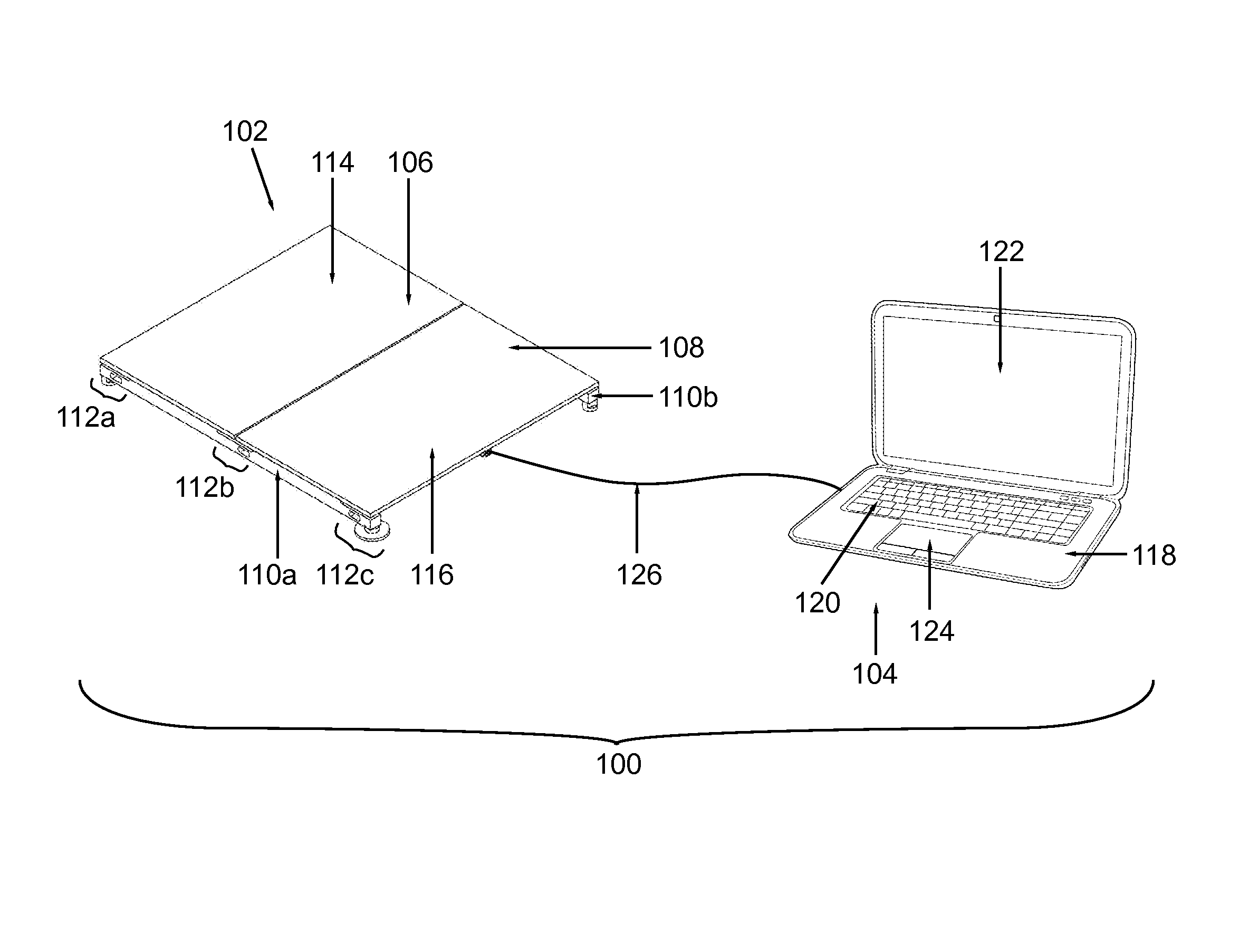
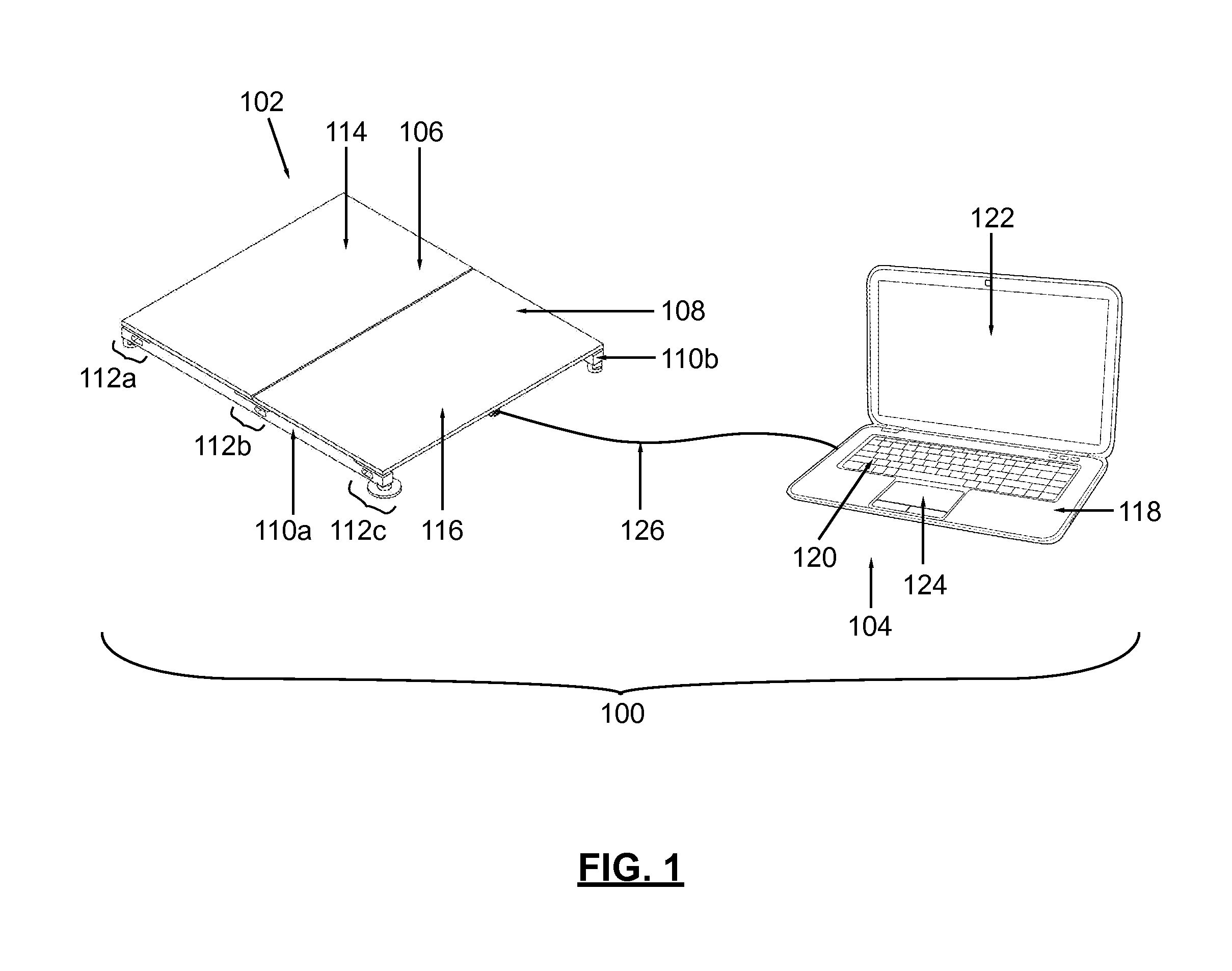
[0071]A first embodiment of a dual force plate system is seen generally at 100 in FIG. 1. The dual force plate system 100 generally comprises a dual force plate assembly 102 operatively coupled to a data acquisition / data processing device 104 (i.e., a data acquisition and processing device) by virtue of an electrical cable 126. In the first embodiment, the dual force plate assembly 102 for receiving a subject utilizes a continuous force transducer beam design. In a preferred embodiment of the invention, the electrical cable 126 is used for data transmission, as well as for providing power to the dual force plate assembly 102. Preferably, the electrical cable 126 contains a plurality of electrical wires bundled together, with at least one wire being used for power and at least another wire being used for transmitting data. The bundling of the power and data transmission wires into a single electrical cable 126 advantageously creates a simpler and more efficient des...

second embodiment

B. Second Embodiment

[0087]A second embodiment of the dual force plate assembly is seen generally at 202 in FIG. 9, and in FIGS. 10 and 11. In accordance with the second embodiment of the invention, a dual force plate system generally comprises the dual force plate assembly 202 of FIG. 9 operatively coupled to a data acquisition / data processing device 104 by virtue of an electrical cable 126 (as illustrated in FIG. 1 for the dual force plate assembly 102). In the second embodiment, the dual force plate assembly 202 for receiving a subject utilizes a plurality of spaced apart, short transducer beams 208, 210, 212 disposed underneath, and near opposite lateral sides of, a first plate component 204 and a second plate component 206. Because the data acquisition / data processing device 104 and the electrical cable 126 are the same as that described above with regard to the first embodiment, a description of these components 104, 126 will not be repeated for this embodiment. Like the dual f...

third embodiment

C. Third Embodiment

[0094]A third embodiment of the dual force plate assembly is seen generally at 302 in FIGS. 12 and 13. In accordance with the third embodiment of the invention, the dual force plate assembly 302 for receiving a subject utilizes continuous force transducer beams 308a, 308b disposed on opposite lateral sides of the first and second plate components 304, 306, rather than force transducer beams disposed underneath the first and second plate components as described with regard to the first and second embodiments of the invention. As explained above in conjunction with the preceding two embodiments, the first plate component 304 has a top surface 312 that is configured to receive a first portion of a body of a subject. Similarly, the second plate component 306 has a top surface 314 that is configured to receive a second portion of a body of a subject. Also, similar to the first two embodiments described above, a continuous narrow gap 320 is provided between the first pl...


PUM

PropertyMeasurementUnit
cutoff frequencyaaaaaaaaaa
weightaaaaaaaaaa

Abstract

A dual force plate system having two independent measurement surfaces is disclosed herein. The dual force plate system includes a first plate component having a first measurement surface for receiving a first portion of a body of a subject, a second plate component having a second measurement surface for receiving a second portion of the body of the subject, a first force transducer element operatively coupled to the first plate component, a second force transducer element operatively coupled to the second plate component, and a third force transducer element operatively coupled to both the first plate component and the second plate component. A force plate system for computing a center of gravity of a subject is also disclosed herein. In addition, a method for determining the center of gravity for a subject disposed on a force measurement assembly is described herein.

Description

CROSS-REFERENCE TO RELATED APPLICATIONS[0001]This patent application is a continuation-in-part application, which is co-pending with, and claims priority from, U.S. Non-Provisional patent application Ser. No. 13 / 348,506, entitled “Force Measurement System Having a Plurality of Measurement Surfaces”, filed on Jan. 11, 2012, which is incorporated by reference herein in its entirety by this reference thereto.STATEMENT REGARDING FEDERALLY SPONSORED RESEARCH OR DEVELOPMENT[0002]Not Applicable.NAMES OF THE PARTIES TO A JOINT RESEARCH AGREEMENT[0003]Not Applicable.INCORPORATION BY REFERENCE OF MATERIAL SUBMITTED ON A COMPACT DISK[0004]Not Applicable.BACKGROUND OF THE INVENTION[0005]1. Field of the Invention[0006]The invention generally relates to force measurement systems. More particularly, the invention relates to a force measurement system that is particularly useful in the assessment of the balance of a subject.[0007]2. Background and Description of Related Art[0008]Force measurement s...

Claims


Application Information

Patent Timeline
Patent Type & Authority Patents(United States)
IPC IPC(8): G01D7/00G01L1/22
CPCA61B5/1036A61B5/4023G01G19/44G01M1/122
Inventor BERME, NECIP
Owner BERTEC
Why Eureka
Try Eureka