Rifle scope turret with spiral cam mechanism

a technology of spiral cam and rifle scope, which is applied in the direction of mountings, optical elements, instruments, etc., can solve the problems of inability to realize the turret has been inadvertently adjusted, the user may lose track of how many rotations the turret has been dialed, and the turret can be easily humped, so as to improve the appreciation of the contribution of the art

Active Publication Date: 2014-12-30
SHELTERED WINGS
View PDF63 Cites 58 Cited by
  • Summary
  • Abstract
  • Description
  • Claims
  • Application Information

AI Technical Summary

Problems solved by technology

Unfortunately, conventional turrets typically omit at least one of the following functions: adjustment stops that prevent adjustment of the elevation and windage turrets beyond preset amounts, rotation indicator / counter, or turret locking.
As a result, users of conventional turrets may lose track of how many rotations are dialed in if he or she does not carefully count the number of rotations both while dialing away from the zero point and when dialing towards the zero point even when the turret's markings are visible.
Furthermore, turrets can be easily humped, and in dark conditions where it may be difficult to see the turret markings, the user may not realize the turrets have been inadvertently adjusted if the turret omits a locking mechanism.
Another difficulty with existing rifle scopes is that certain operating conditions require the user to remember both how many clicks and the direction of rotation needed to return the elevation turret to its zero point from a different setting.
When light conditions are poor, such as at twilight, night, or in darkened rooms of buildings, or if it is difficult for the user to hear or feel the clicks, it is very easy for the user to lose track of what adjustment is needed to return to the zero point.
This is particularly significant for police and military users of firearms, who in the course of their duties may very likely be confronted with a threat under poor lighting conditions.
Because of the need for compact riflescope components, markings are necessarily small, making them difficult to read under borderline conditions.
White this may be a concern when making fine adjustments, it is of greater concern when a user must make large changes involving several revolutions of a knob, which may lead to an error in the number of revolutions made.

Method used


Image

  • Rifle scope turret with spiral cam mechanism
  • Rifle scope turret with spiral cam mechanism
  • Rifle scope turret with spiral cam mechanism

Examples


Embodiment Construction

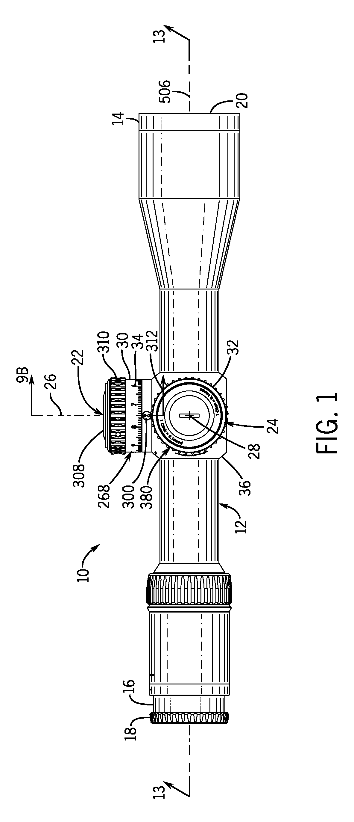
[0033]A preferred embodiment of the rifle scope with spiral cam mechanism of the present invention is shown and generally designated by the reference numeral 10.

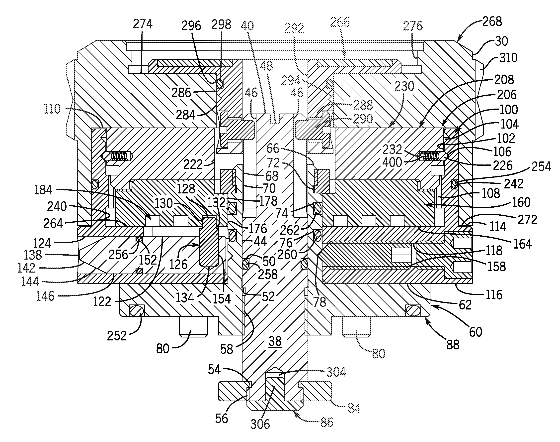
[0034]FIG. 1 illustrates the improved rifle scope with spiral cam mechanism 10 of the present invention. More particularly, the rifle scope 10 has a scope body 12 that encloses a movable optical element 248 (shown in FIG. 13), which is an erector tube. The scope body is an elongate tube having a larger opening at its front 14 and a smaller opening at its rear 16. An eyepiece 18 is attached to the rear of the scope body, and an objective lens 20 is attached to the front of the scope body. The center axis of the movable optical element defines the optical axis 506 of the rifle scope.

[0035]An elevation turret 22 and a windage turret 24 are two knobs in the outside center part of the scope body 12. They are marked in increments by indicia 34 on their perimeters 30 and 32 and are used to adjust the elevation and windage of the mo...


PUM


Abstract

Rifle scope turrets with spiral cam mechanisms include a scope body, a movable optical element defining an optical axis enclosed by the scope body, and a turret having a screw operably connected to the optical element for adjusting the optical axis in response to rotation of the screw. The turret has a spiral cam mechanism engaged thereto. The turret defines first and second stop surfaces positioned for engagement by the spiral cam to limit rotation of the turret. The first stop surface defines a zero position of the screw and the movable optical element. The second stop surface defines a maximum point of displacement of the screw and the moveable optical element. The stop surfaces may be defined by a spiral cam groove in the indexing portion of the turret. The groove may overlap itself at least partially. The turret may be an elevation turret or a windage turret.

Description

FIELD OF THE INVENTION[0001]The present invention relates to a rifle scope turret that uses a spiral cam mechanism to achieve multiple functions: adjustment stops that prevent adjustment of the elevation and windage turrets beyond preset amounts, rotation indicator / counter, and turret locking.BACKGROUND OF THE INVENTION[0002]A turret is one of two knobs in the outside center part of a riflescope body. Turrets are marked in increments and are used to adjust elevation and windage for points of impact change. Conventional turrets have markings on them that indicate how many clicks of adjustment have been dialed in on the turret, or an angular deviation, or a distance compensation for a given cartridge. A click is one tactile adjustment increment on the windage or elevation turret of a scope.[0003]In order to achieve accurate sighting of objects at greater distances, the downward acceleration on the projectile imparted by gravity is of greater significance. The effect of gravity on a pr...

Claims


Application Information

Patent Timeline
Patent Type & Authority Patents(United States)
IPC IPC(8): F41G1/38
CPCG02B23/16F41G1/38G02B7/023G02B23/14
Inventor HAMILTON, SAMUEL, J.
Owner SHELTERED WINGS
Why Eureka
Try Eureka