Arrangement of a rail and a slip contact holder mounted thereon

a technology of slip contact and mounting bracket, which is applied in the direction of railway tracks, runways, constructions, etc., can solve the problems of inability to access the upper profile walls of the profile body, the inability to easily use the rails, and the inability to easily reach the inside, so as to achieve simple and secure attachment

Active Publication Date: 2014-12-30
KONECRANES GLOBAL
View PDF79 Cites 4 Cited by
  • Summary
  • Abstract
  • Description
  • Claims
  • Application Information

AI Technical Summary

Benefits of technology

[0013]The invention provides an arrangement consisting of a rail and a contact line holder attached thereto, which offers simple and secure attachment of the contact line.
[0019]In an embodiment provision is made for the latching lugs to be disposed in pairs on the contact line holder for engagement into two of the punch-outs. This produces simple and secure holding and the contact line holder is held in a stable and non-rotatable manner. In other words, there are pairs of mutually opposing latching lugs and punch-outs disposed on the left and right of the longitudinal middle plane respectively. In a preferred manner, the barb-like protrusions are oriented away from each other in each case in order to engage behind the profiled sheet metal. The barb-like protrusions are usefully chamfered in the longitudinal direction of the latching lugs so that they can easily be introduced into the punch-outs. In addition, it is useful for the individual latching lugs to be pretensioned away from each other so that secure engagement behind the profile walls is achieved.

Problems solved by technology

Although this construction has proved its worth, it is not readily usable with rails in which there is no access or only poor access to the upper profile walls from the outside, as is the case with double-chamber rails.
Therefore the upper profile walls of the profile body are not readily accessible for screw attachment since they are covered by the profile head.
On the other hand, accessibility from inside is practically impossible since the lower slot of such rails hardly allows any access owing to its narrow width.

Method used


Image

  • Arrangement of a rail and a slip contact holder mounted thereon
  • Arrangement of a rail and a slip contact holder mounted thereon
  • Arrangement of a rail and a slip contact holder mounted thereon

Examples


Embodiment Construction

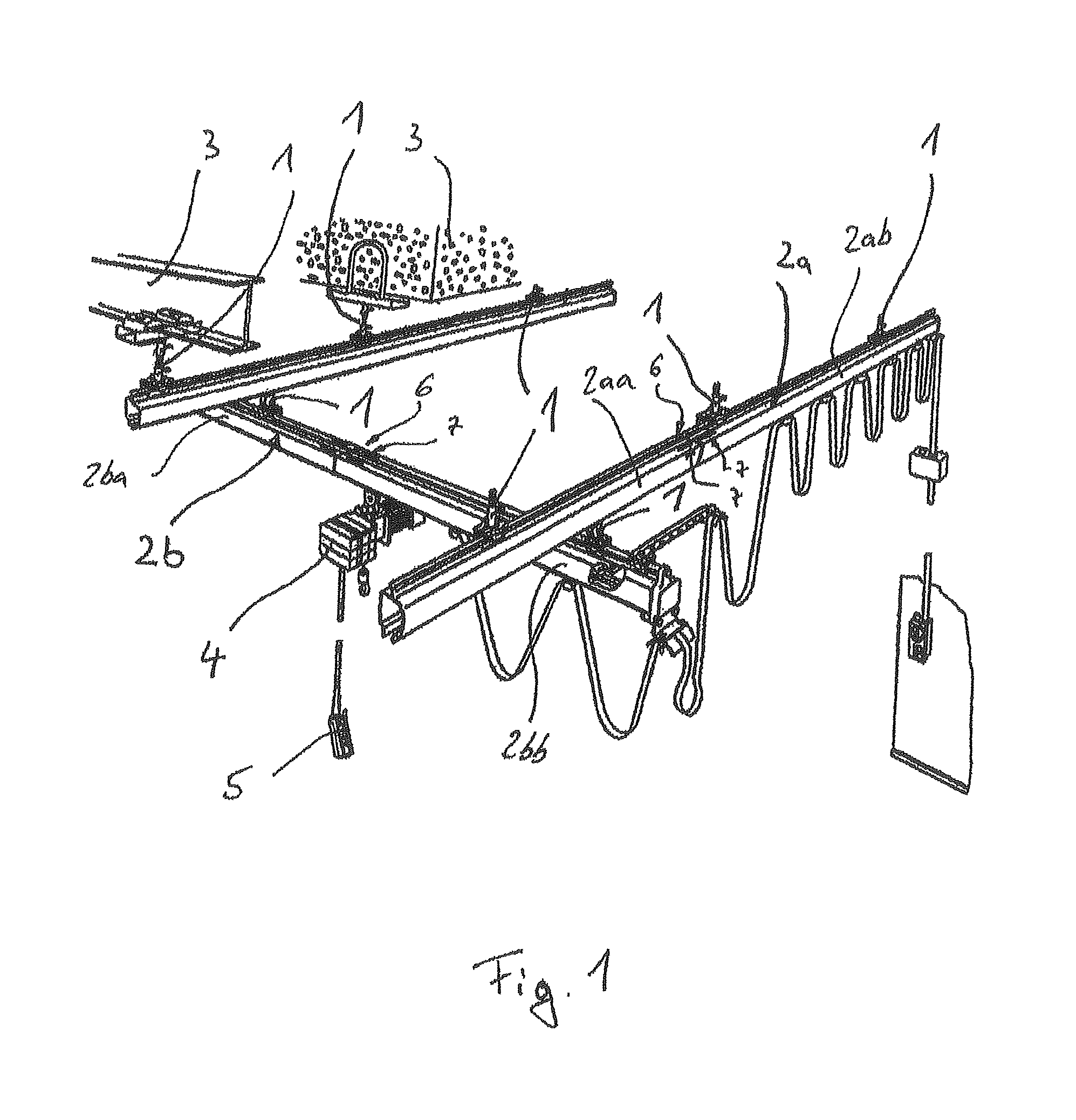
[0027]In order to illustrate the widest range of possible uses of connected rail sections to form rails, in FIG. 1 a single-girder suspension crane according to the prior art is shown.

[0028]By virtue of suspension means 1, essentially horizontally extending c-shaped profiled rails 2, which are open in the downwards direction, are suspended on bearing elements 3 or further rails 2. The bearing elements 3 are formed as I beams. Since the present exemplified embodiment relates to a single-girder suspension crane, two first rails 2a, which extend essentially horizontally, in parallel and spaced apart from each other, are provided and serve as rails for the single-girder suspension crane, as is a second rail 2b, which forms a crane rail, which is oriented essentially transverse to the first rails 2a and can travel along the first rails 2a. For this purpose the second rail 2b is suspended via two suspension means 1 in each case on a travelling mechanism, not shown, which can travel along ...


PUM


Abstract

An arrangement of a rail for suspended conveyors or suspended cranes and a slip contact holder mounted thereon, wherein the rail comprises a profile body and a profile head connected thereto and disposed above the profile body, wherein the profile body is C-shaped in cross section, forms a hollow space for chassis, and has a slit open to the bottom, and the profile head comprises upper, substantially horizontal profile walls and the slip contact holder is disposed within the hollow space and attached to the upper profile walls. A plurality of punchouts are disposed in the upper profile walls, disposed in at least one row and at regular, repeated distances as seen in the longitudinal direction of the rail, and barb-like catch pawls are disposed on the slip contact bolder and engage with the punchouts in order to attach thereto.

Description

CROSS REFERENCE TO RELATED APPLICATIONS[0001]The present application claims the priority benefits of International Patent Application No. PCT / EP2011 / 065327, filed on Sep. 5, 2011, and also of German Patent Application No. DE 10 2010 037 520.9, filed on Sep. 14, 2010, which are hereby incorporated herein by reference in their entireties.BACKGROUND OF THE INVENTION[0002]The invention relates to an arrangement consisting of a rail for suspended tracks or suspension cranes and a contact line holder attached thereto, wherein the rail has a profile body and a profile head connected thereto and disposed above the profile body, wherein the profile body is c-shaped when seen in cross-section, forms a hollow chamber for travelling mechanisms and is formed with a slot open in the downwards direction, the profile body has upper profile walls extending essentially horizontally, and the contact line holder is disposed inside the hollow chamber in the region of the upper profile walls and is attac...

Claims


Application Information

Patent Timeline
Patent Type & Authority Patents(United States)
IPC IPC(8): B66C7/08E01B25/24B66C7/02H02G5/04
CPCH02G5/04B66C7/02E01B25/24B66C7/08
Inventor SPIES, GERDFITZLER, STEFANMULLER, SVEN
Owner KONECRANES GLOBAL
Why Eureka
Try Eureka