Parked vehicle detection based on edge detection

Inactive Publication Date: 2014-12-30
CHENGDU HAICUN IP TECH +1
41 Cites 17 Cited by

AI-Extracted Technical Summary

Problems solved by technology

Locating a vacant parking space causes much frustration to motorists.
It increases fuel consumption and has a negative impact to the environment.
This operation requires significant amount of man power and also consumes a lot of fue...

Benefits of technology

[0010]It is a principle object of the present invention to conserve energy resources and enhance the quality of the environment.
[0011]It is a further object of the present invention to provide a robust parking-detection method.
[0012]It is a further object of the present invention to provide a parking-detection method insensitive to viewing angle, shadow, lighting variations and surface conditions.
[0013]In accordance with these and other objects of the present invention, the present invention discloses a parking-detection method based on edge detection.
[0014]The present invention discloses a parking-detection method based on edge detection. A parking-monitoring camera captures an image of a parking area including a plurality of parking spaces. In the image of each parking space, its boundary comprises an exposed edge (which is not occluded by any parked vehicles) and a secondary edge (which might be occluded by a parked vehicle and is not parallel to the exposed edge). A processor processes the captured image and uses an edge-detection algorithm to detect edges within the ROI associated with each parking space....

Abstract

The present invention discloses a method for detecting parked vehicles based on edge detection. For each parking space, its boundary comprises an exposed edge, which is not occluded by any parked vehicle. Its primary detected edges are the detected edges that are substantially parallel to the exposed edge. A parking space is detected as occupied if its primary detected edges satisfy at least one of these conditions: (1) their total number is more than a pre-determined minimum number; and/or, (2) their total length is more than a pre-determined minimum length.

Application Domain

Image analysisDetection of traffic movement +3

Technology Topic

Parking spaceEngineering +3

Image

  • Parked vehicle detection based on edge detection
  • Parked vehicle detection based on edge detection
  • Parked vehicle detection based on edge detection

Examples

  • Experimental program(1)

Example

[0023]It should be noted that all the drawings are schematic and not drawn to scale. Relative dimensions and proportions of parts of the device structures in the figures have been shown exaggerated or reduced in size for the sake of clarity and convenience in the drawings. The same reference symbols are generally used to refer to corresponding or similar features in the different embodiments.
DETAILED DESCRIPTION OF THE PREFERRED EMBODIMENTS
[0024]Those of ordinary skills in the art will realize that the following description of the present invention is illustrative only and is not intended to be in any way limiting. Other embodiments of the invention will readily suggest themselves to such skilled persons from an examination of the within disclosure.
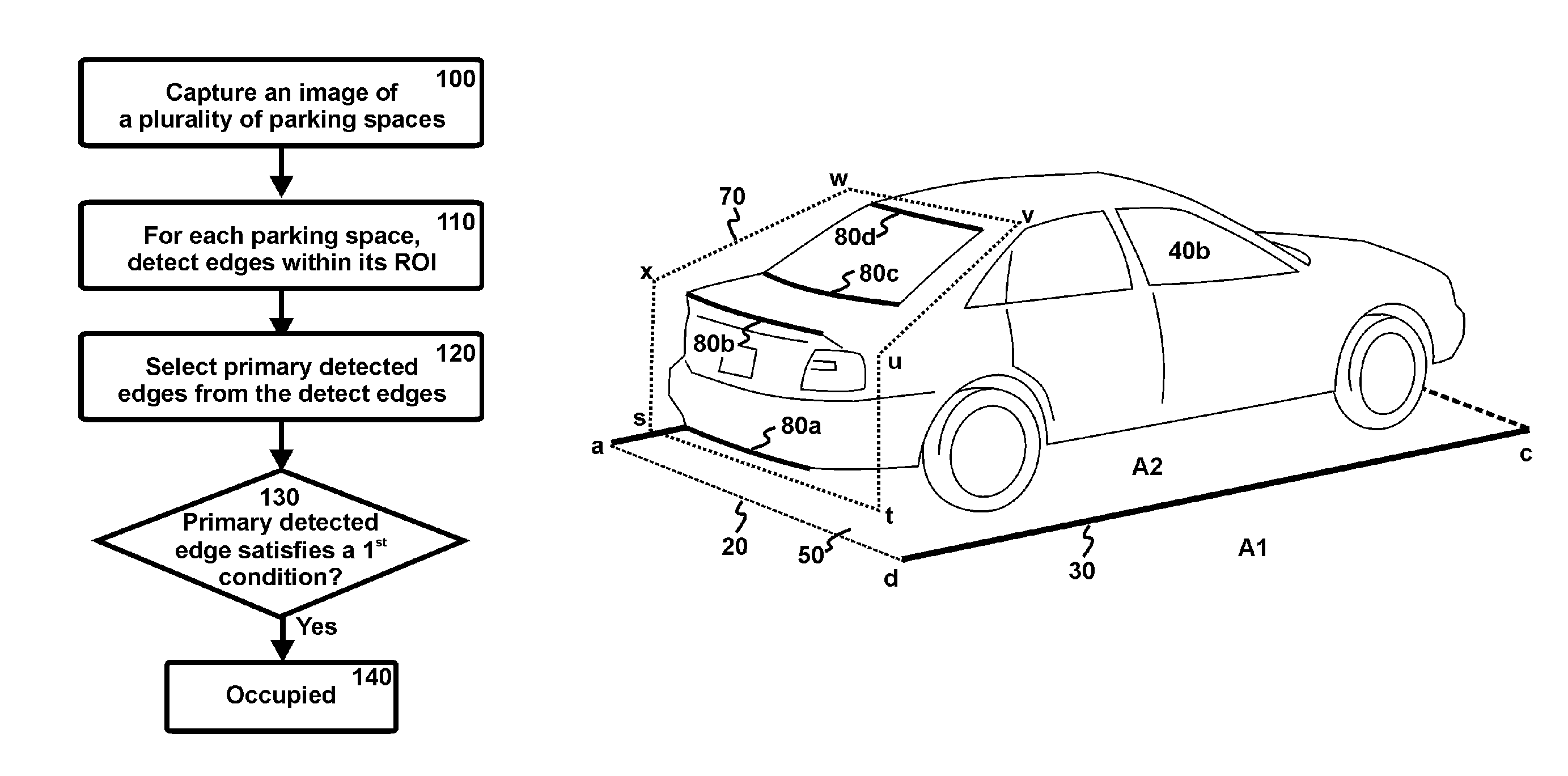
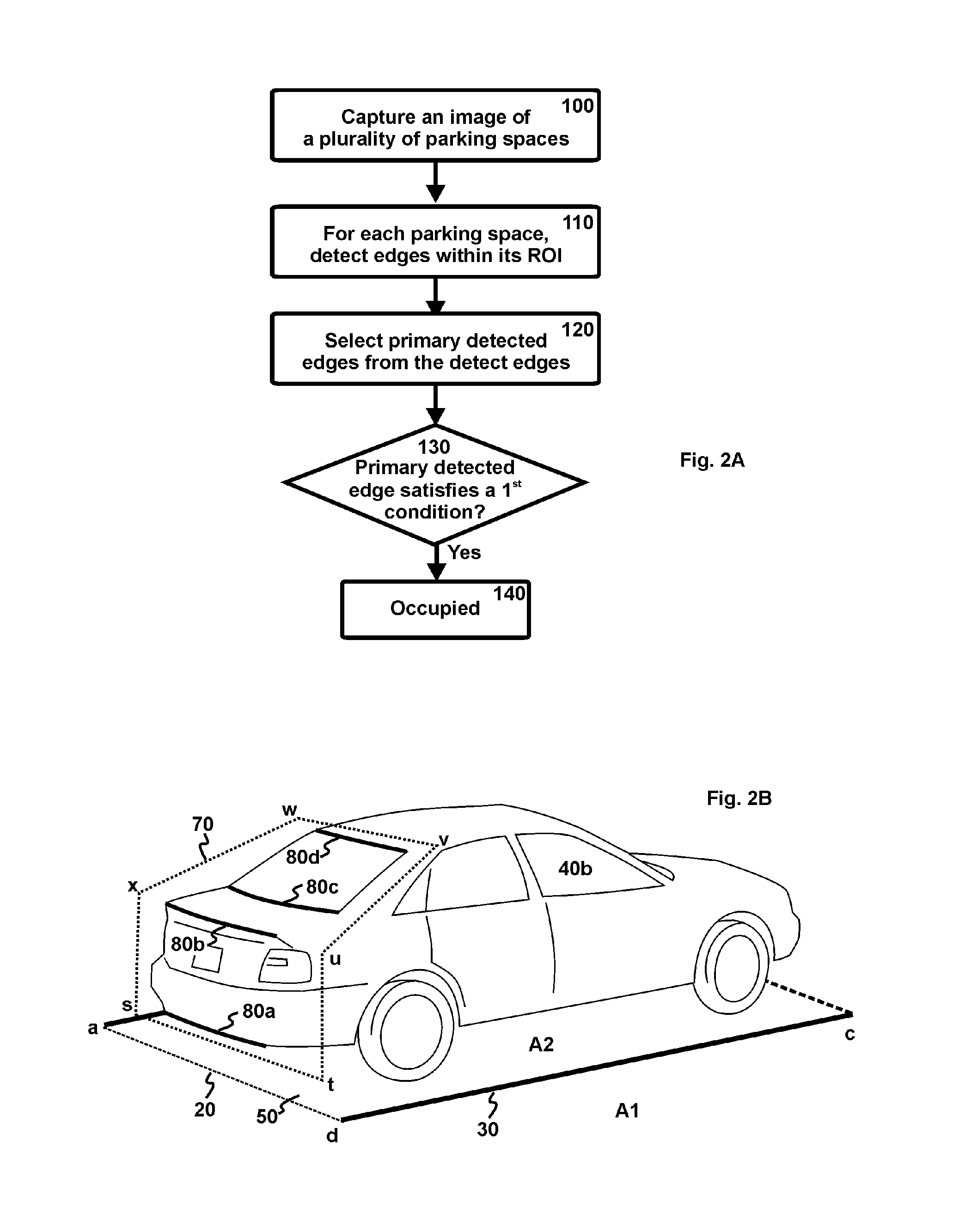
[0025]Referring now to FIGS. 2A-2B, FIG. 2A discloses a flow chart showing preferred steps to detect a parking space A2 which is occupied by a vehicle 40b; FIG. 2B illustrates the primary detected edges 80a-80d within its ROI 70. In this example, the vehicles (40b. . . ) parked in the parking spaces A1-A4 are parked in parallel, i.e. side-by-side parking.
[0026]During parking detection, a parking-monitoring camera captures an image of a parking area including a plurality of parking spaces A1, A2 (step 100). In the image 50 of each parking space (e.g. A2), its boundary comprises an exposed edge 20 (line “ad”) and at least a secondary edge 30 (line “cd”). The exposed edge 20 is not occluded by any parked vehicles (as shown in FIGS. 1A-1B), while the secondary edge 30 might be occluded by a parked vehicle (e.g. 40a of FIG. 1A) and is not parallel to the exposed edge 20. A processor processes the captured image and uses an edge-detection algorithm to detect edges within the ROI 70 associated with the parking space A2 (step 110). Among these detected edges, the primary detected edges 80a-80d are selected from those that are substantially parallel to the exposed edge 20 (step 120). These primary detected edges 80a-80d are also referred to as the signature edges of the detected vehicle 40b. They correspond to the bottom edge of the rear bumper, the protruded edge of the trunk, the bottom edge of the rear window, and the top edge of the rear window of the detected vehicle 40b, respectively. If the primary detected edges 80a-80d satisfy a first condition (step 130), the parking space A2 is detected as occupied (step 140). The first condition could be any or a combination of: (1) the total number of the primary detected edges is more than a first pre-determined minimum number; (2) the total length of the primary detected edges is more than a first pre-determined minimum length.
[0027]In FIG. 2B, the ROI 70 associated with the parking space A2 is designed in such a way that the occlusion of a front-parked vehicle (e.g. 40a of FIG. 1A) does not interfere with the vehicle detection for the parking space A2. Here, a front-parked vehicle is a vehicle parked immediately in front of the parking space of interest from the perspective of the camera. In this example, the ROI 70 takes a hexagonal shape “stuvwx”. It is formed by scanning at least a portion of the exposed edge 20 upward and then side-way.
[0028]Referring now to FIGS. 3A-3B, FIG. 3A discloses a flow chart showing preferred steps to detect a vacant parking space A2; FIG. 3B illustrates the secondary detected edges 90a-90b within its ROI 70. Among the detected edges, the secondary detected edges 90a-90b are selected from the detected edges that are substantially parallel to the secondary edge 30 (step 150). They correspond to the line “ab” separating the parking spaces A2/A3, the bottom edge of the body of a back-parked vehicle 40c, respectively. Here, a back-parked vehicle is a vehicle parked immediately behind the parking space of interest from the perspective of the camera. If the secondary detected edges 90a-90b satisfy a second condition (step 160), the parking space A2 is vacant (step 170). The second condition could be any or a combination of: (1) the total number of the secondary detected edges is more than a second pre-determined minimum number; (2) the total length of the secondary detected edges is more than a second pre-determined minimum length.
[0029]Referring now to FIGS. 4A-4C, the term “substantially parallel” is further explained. This term is commonly used in the definition of primary detected edges and secondary detected edges. In a first preferred definition of FIG. 4A, a curve 80 is substantially parallel to a line 20 if the tangential angle θ at any given pixel Z along the curve 80 is within a pre-determined range from the directional angle β of the line 20. In a second preferred definition of FIG. 4B, a curve 80 is substantially parallel to a line 20 if the directional angle α of the best-fit line 80* to the curve 80 is within another pre-determined range from the directional angle β of the line 20. In a third preferred definition of FIG. 4C, a curve 80 is substantially parallel to a line 20 if a shifted line 80x can be found which is parallel to the line 20 and any pixel Z along the curve 80 is within a pre-determined distance to the shifted line 80x. Here, the angles (including tangential angle and directional angle) are measured with respect to the +x axis in these figures. It should be apparent to those skilled in the art that, besides the above three definitions, other definition may also be used.
[0030]Referring now to FIG. 5, the primary detected edges for a tail-in-first vehicle are disclosed. Like that in FIG. 2B, the vehicle 40b* is parked side-by-side with other vehicles in the parking spaces A1-A4. However, instead of being parked head-in-first, it is parked tail-in-first, i.e. the vehicle's head is towards the exposed edge 20. Within the ROI 70, the primary detected edges 80e, 80f correspond to the bottom edge of the front bumper and the bottom edge of the front window of the vehicle 40b*. These primary detected edges 80e, 80f are also the signature edges of the detected vehicle 40b*.
[0031]Besides side-by-side parking (FIGS. 2B, 3B and 5), the preferred edge-detection algorithm can be used to detect series-parked vehicles, which are parked one after another in succession. Most street parking is series parking. FIG. 6A illustrates an example. In this example, the vehicles (40x. . . ) parked in the parking spaces B1, B2 are parked in series along a curb 10. The parking space B2 is occupied by a vehicle 40x and its boundary comprises an exposed edge 20 (line “ef”) and a secondary edge 30 (line “eg”). The ROI 70 associated with the parking space B2 is formed by scanning at least a portion of the exposed edge 20 upward. Within the ROI 70, the primary detected edges 80x, 80y are signature edges of the detected vehicle 40x. They correspond to the bottom edge of the body and the bottom edge of the side window of the detected vehicle 40x. Similar to FIG. 2B, the parking space B1 is detected as occupied if the primary detected edges 80x, 80y satisfy a first condition: (1) the total number of the primary detected edges is more than a first pre-determined minimum number; and/or, (2) the total length of the primary detected edges is more than a first pre-determined minimum length.
[0032]FIG. 6B illustrates the secondary detected edges 90x within an ROI 70 when the parking space B1 is vacant. Note that a back-parked vehicle 40y may interfere with the vehicle detection for the parking space B1. Within the ROI 70, the secondary detected edge 90x correspond to the bottom edge of the body of the back-parked vehicle 40y. Similar to FIG. 3B, the parking space B1 is detected as vacant if the secondary detected edges 90x satisfy a second condition: (1) the total number of the secondary detected edges is more than a second pre-determined minimum number; and/or, (2) the total length of the secondary detected edges is more than a second pre-determined minimum length.
[0033]While illustrative embodiments have been shown and described, it would be apparent to those skilled in the art that may more modifications than that have been mentioned above are possible without departing from the inventive concepts set forth therein. The invention, therefore, is not to be limited except in the spirit of the appended claims.

PUM

no PUM

Description & Claims & Application Information

We can also present the details of the Description, Claims and Application information to help users get a comprehensive understanding of the technical details of the patent, such as background art, summary of invention, brief description of drawings, description of embodiments, and other original content. On the other hand, users can also determine the specific scope of protection of the technology through the list of claims; as well as understand the changes in the life cycle of the technology with the presentation of the patent timeline. Login to view more.

Similar technology patents

Plant lighting apparatus

InactiveUS20160192597A1enhance quality
Owner:CAL COMP BIOTECH

Method for making foamed products

InactiveUS20060043642A1enhance qualityefficiently use
Owner:YANG CHI HSIUNG

Classification and recommendation of technical efficacy words

  • enhance quality

Controllable waveguide for near-eye display applications

ActiveUS20140300966A1enhance qualityexpand view area
Owner:VUZIX

Methods and Systems for Methylotrophic Production of Organic Compounds

InactiveUS20150315599A1enhance qualityavoid production
Owner:GINKGO BIOWORKS INC

Automated photo-product specification method

InactiveUS20130050747A1enhance quality
Owner:INTELLECTUAL VENTURES FUND 83 LLC

Micro-endoscopic system

InactiveUS6561973B1efficient and cost effective constructionenhance quality
Owner:MICRO INVASIVE TECH
Why Eureka
Try Eureka