
Navigation device, navigation method, and navigation program

a navigation device and navigation method technology, applied in navigation instruments, surveying and navigation, instruments, etc., can solve problems such as difficult to provide guidance to drivers, and give drivers an uncomfortable feeling

Inactive Publication Date: 2014-12-30
AISIN AW CO LTD
View PDF13 Cites 2 Cited by
  • Summary
  • Abstract
  • Description
  • Claims
  • Application Information

AI Technical Summary

Benefits of technology

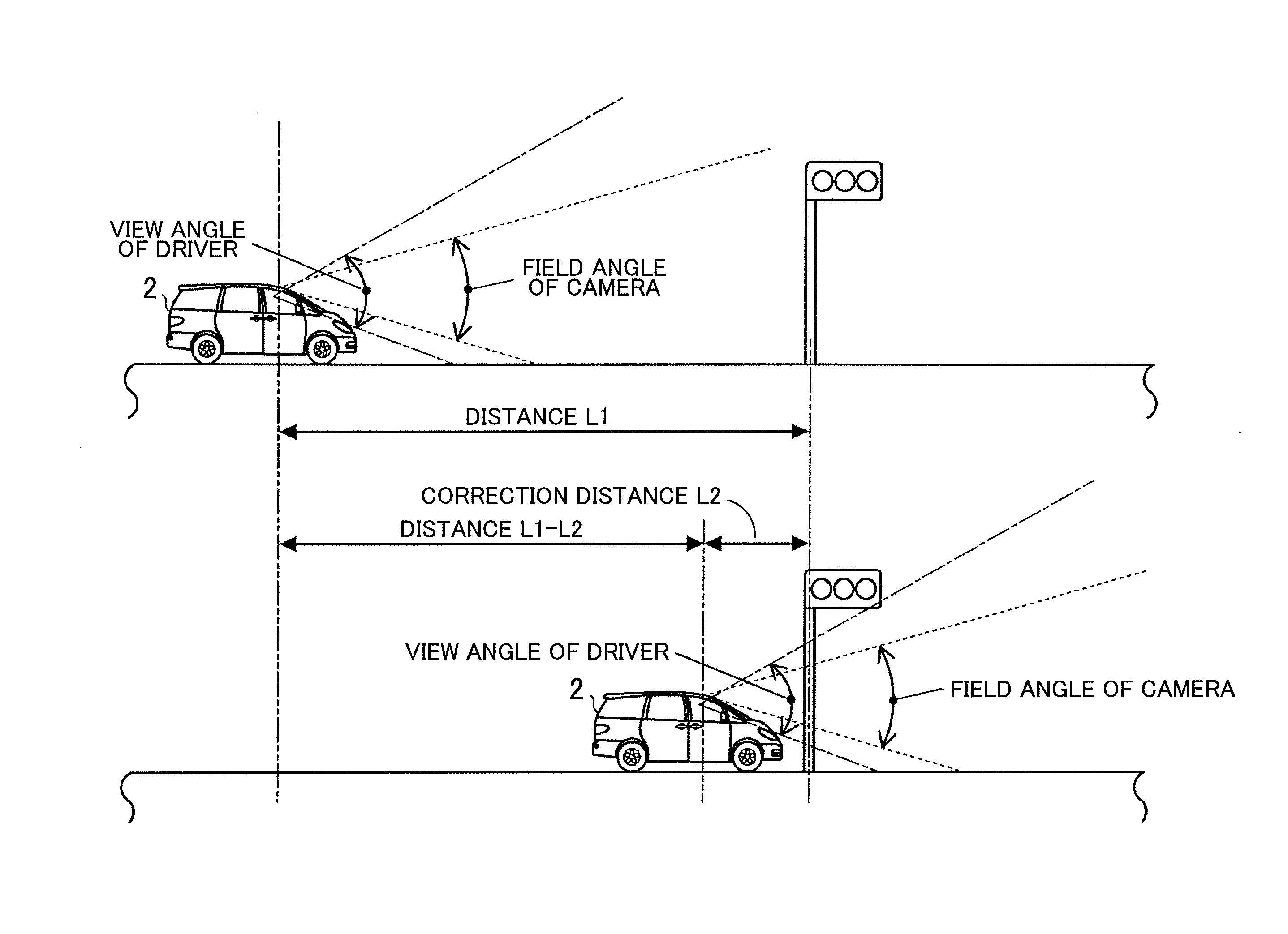
[0014]According to the navigation device described in the first aspect of the present invention, the navigation method described in the fifth aspect of the present invention, and the navigation program described in the sixth aspect of the present invention, if the judging unit has judged that the vehicle has arrived at the second vehicle position, the guidance unit provides guidance regarding the feature at the predetermined position having the second vehicle position as a reference. Therefore, even if the field angle of the image-capturing unit and the view angle of the driver are different, the guidance can be provided based on the time when the feature disappears from the driver's view. Thereby, it is possible to provide the guidance to the driver at an appropriate time.
[0015]According to the navigation device described in the second aspect of the present invention, the correction distance is the distance from the second vehicle position to the position of the feature, and the judging unit determines the position of the feature based on the captured image acquired by the image acquiring unit, and if the vehicle has arrived at a position by the correction distance before the determined position of the feature along the travel direction of the vehicle, judges that the vehicle has arrived at the second vehicle position. Therefore, even if the vehicle is traveling the position well before the feature, the second vehicle position can be determined. Thereby, it is possible to provide the guidance to the user at a more appropriate time.
[0016]According to the navigation device described in the third aspect of the present invention, the correction distance is the distance from the first vehicle position to the second vehicle position, and the judging unit determines, based on the image acquired by the image acquiring unit, a position where the feature has disappeared from the imaging area of the image-capturing unit, and if the vehicle has arrived at a position by the correction distance ahead of the determined position along the travel direction of the vehicle, judges that the vehicle has arrived at the second vehicle position. Therefore, if the vehicle is traveling the position well before the feature and the image of the feature cannot be captured (for example, if the image of a distant feature cannot be captured because of a huge truck traveling ahead of the vehicle), the second vehicle position can be determined. Thereby, it is possible to provide the guidance to the driver at a more appropriate time.
[0017]According to the navigation device described in the fourth aspect of the present invention, the correction distance storing unit stores the correction distance according to the travel speed of the vehicle, and the judging unit determines the travel speed of the vehicle in a predetermined method, acquires the correction distance according to the determined travel speed from the correction distance storing unit, and performs judgment based on the acquired correction distance. Therefore, the second vehicle position can be determined in consideration of the influence that the travel speed makes on the view angle of the driver. Thereby, it is possible to provide the guidance to the driver at a more appropriate time.

Problems solved by technology

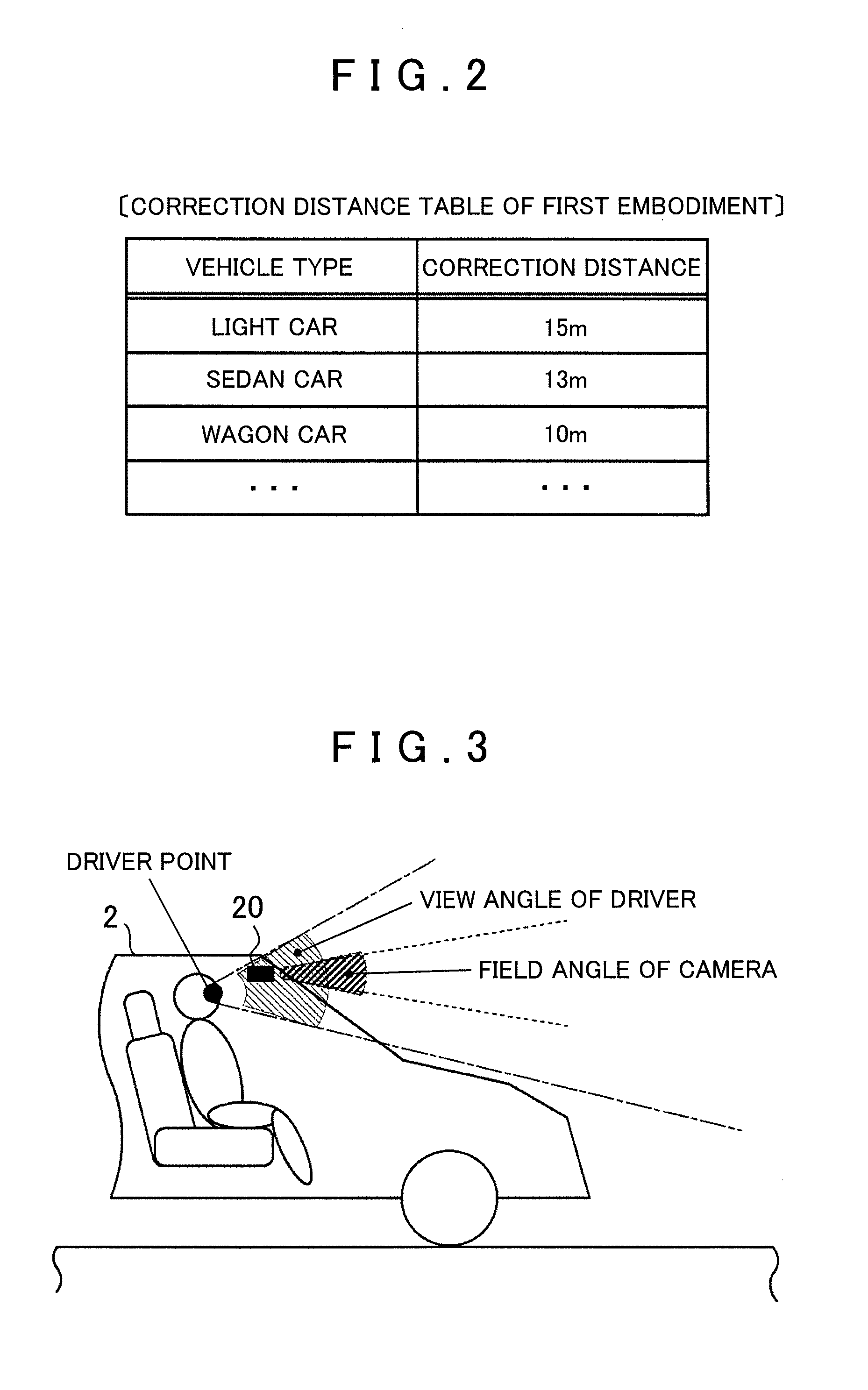
However, in the conventional vehicle position recognizing devices as described above, it can be difficult to provide guidance to the driver at an appropriate time because a gap occurs between the image captured by the image-capturing device and the image that the driver of the vehicle sees, which is caused by a difference between the field angle of the image-capturing device and the view angle of the driver of the vehicle.
For example, when the guidance is provided at the time when the target feature has disappeared from the imaging area of the image-capturing device, if the field angle of the image-capturing device is narrower than the view angle of the driver, the guidance will be provided even when the target feature is still in the driver's view, which gives the driver an uncomfortable feeling.

Method used


Image

  • Navigation device, navigation method, and navigation program
  • Navigation device, navigation method, and navigation program
  • Navigation device, navigation method, and navigation program

Examples


modification examples

for the Embodiment

[0102]While various features have been described in conjunction with the various embodiments of the present invention, various modifications and / or improvements may be made without departing from the broad spirit and scope of the underlying principles described in claims. Some examples of these alternatives are described below.

Problems to be Solved by the Invention and its Effects

[0103]Problems to be solved by the invention and effects of the invention are not limited to the contents described above, and may vary depending on the environment where the invention is executed and / or details of the configuration. Therefore, only a part of the problems described above may be solved, or only a part of the effects described above may be accomplished.

Combination of the Respective Embodiments

[0104]The configurations explained in the respective embodiments can be combined each other in an arbitrary manner. For example, in the third embodiment, a case was explained, in which ...


PUM


Abstract

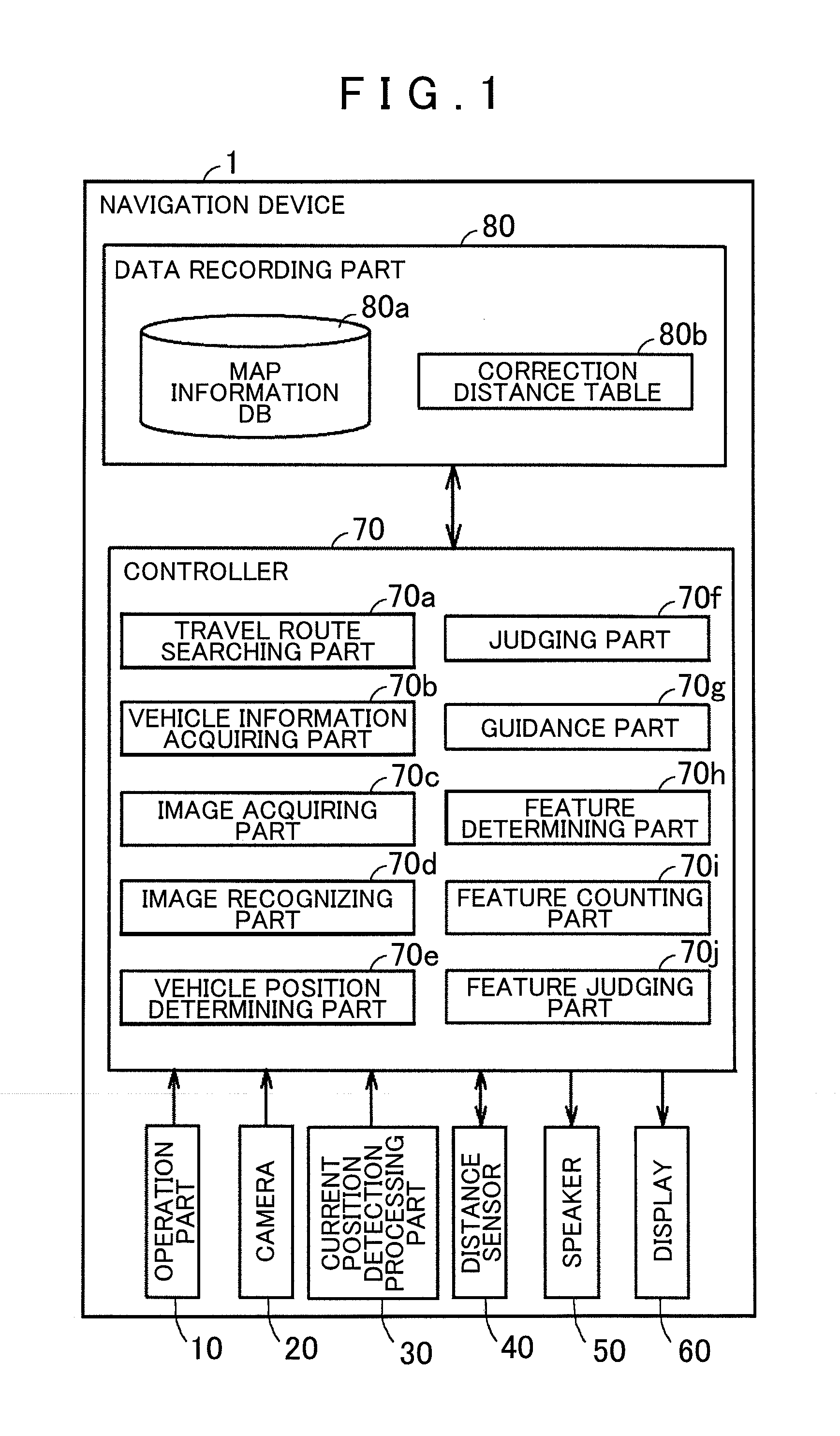
A navigation apparatus and method are provided. The navigation apparatus includes an image acquiring part that acquires an image of a road feature from a vehicle camera. The apparatus also includes a correction distance table that stores a correction distance to correct a difference between a position of a vehicle when the feature disappears from an imaging area of the camera and a guidance output reference position that is a position of the vehicle when the feature disappears from a driver's view. Further, a judging part is included and judges, based on the image acquired by the image acquiring part and the correction distance stored in the correction distance table, whether the vehicle has arrived at the guidance output reference position. Lastly, the apparatus includes a guidance part that provides guidance regarding the traffic light at a predetermined position having the guidance output reference position as a reference.

Description

INCORPORATION BY REFERENCE[0001]This application claims priority from Japanese Patent Application No. 2010-292199, filed on Dec. 28, 2010, including the specification, drawings and abstract thereof, the disclosure of which is incorporated herein by reference in its entirety.BACKGROUND OF THE INVENTION1. Field of the Invention[0002]Aspects of the present invention relate to a navigation device, a navigation method, and a navigation program.[0003]Conventionally, navigation devices are used that store map information including road data, facility data, and the like, and provide guidance on a route based on the map information. For example, these navigation devices may determine a vehicle position on a map though map-matching between map data corresponding to a route and a current position detected by a current position detector and provide guidance based on the determined vehicle position.[0004]However, in these navigation devices, guidance may be provided at a point a few dozens of me...

Claims


Application Information

Patent Timeline
Patent Type & Authority Patents(United States)
IPC IPC(8): G01C21/36
CPCG01C21/3602G01C21/3644G01C21/3655
Inventor OKABE, HIDEFUMISATO, YUJI
Owner AISIN AW CO LTD
Learn More