Connecting device

a technology of connecting device and longitudinal axis, which is applied in the direction of vehicle maintenance, vehicle cleaning, domestic applications, etc., can solve the problems of limited torsional movement around the longitudinal axis, and achieve the effects of reducing the stiffness of the adapter, reducing bearing friction, and increasing wall thickness

Active Publication Date: 2015-01-13
ROBERT BOSCH GMBH
View PDF9 Cites 21 Cited by
  • Summary
  • Abstract
  • Description
  • Claims
  • Application Information

AI Technical Summary

Benefits of technology

[0009]According to the invention, the outwardly facing walls of the adapter, namely the side walls, the top wall and the end walls have a general wall thickness of at least two millimeters. In addition, the hubs are formed as blind holes, the cylindrical surfaces of which form radial sliding surfaces and the end faces of which form axial sliding surfaces, which are highly polished with an arithmetic mean roughness of Ra<0.2μ. The sliding surfaces are furthermore the sole contact surfaces between the connecting element and the adapter. In this regard, the sliding surfaces on the end faces of the hinge shaft and on the bottom of the blind holes act as axial bearings, whereas the radial sliding surfaces on the cylindrical surfaces of the hubs and on the periphery of said hinge shaft serves as radial bearings. Low bearing friction and a precise guidance between said hinge shaft and the hubs are achieved by the special surface quality in the bearing area. Because the contact between the adapter and the connecting element is limited to the aforementioned sliding surfaces, no further frictional losses occur in the connecting device according to the invention. The inherently reduced stiffness of the adapter due to the omission of transverse walls is compensated by the greater wall thickness of the outwardly facing walls. This further has the advantage that the connection of the hubs is relatively rigid when the flexibility of the side walls is sufficient in the region of said hubs so that a loss in the support or lateral guidance in the event of impact or a blockage of the windshield wiper is not of concern. Finally lateral spring tongues are eliminated, which can easily break if installation is not performed with care.

Problems solved by technology

Furthermore in connection with the precise mounting and guidance of the wiper blade provided by the high-quality bearing support of the hinge shaft, the possible torsional movement around the longitudinal axis is limited.

Method used


Image

  • Connecting device
  • Connecting device
  • Connecting device

Examples


Embodiment Construction

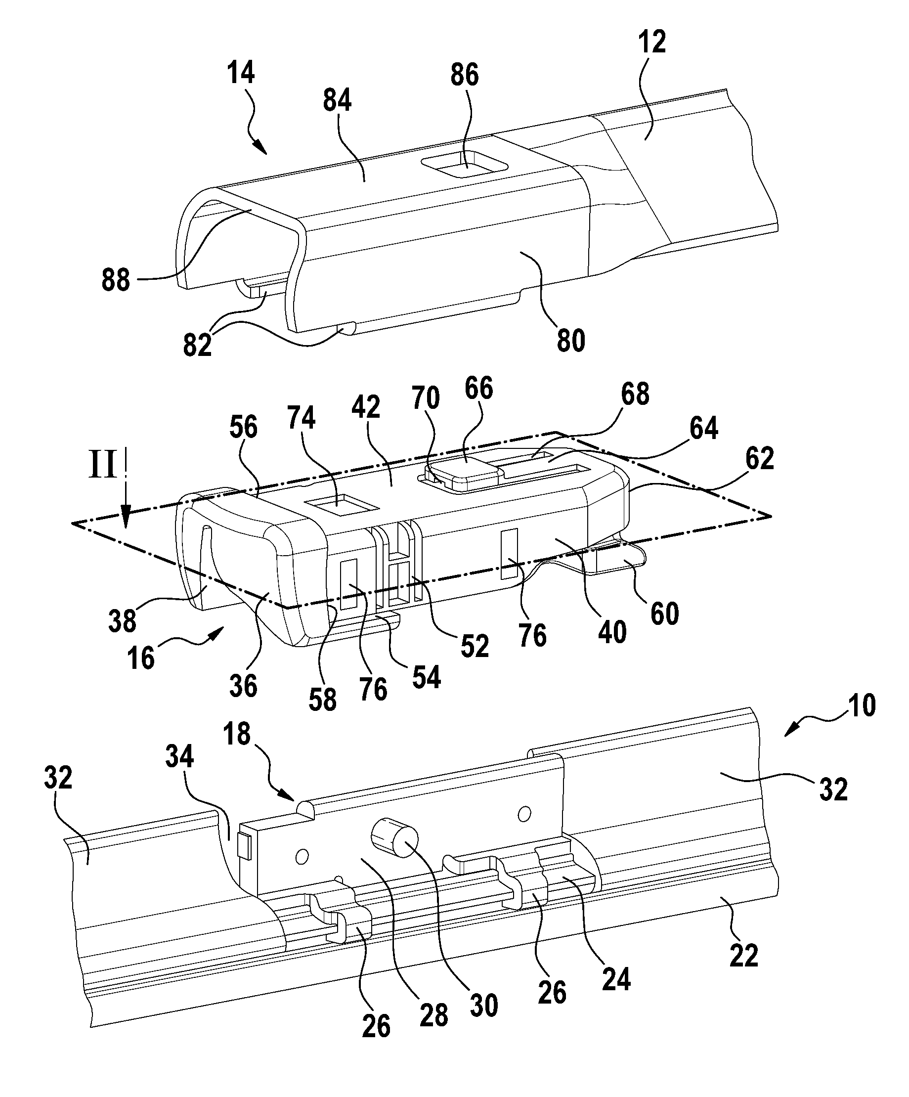
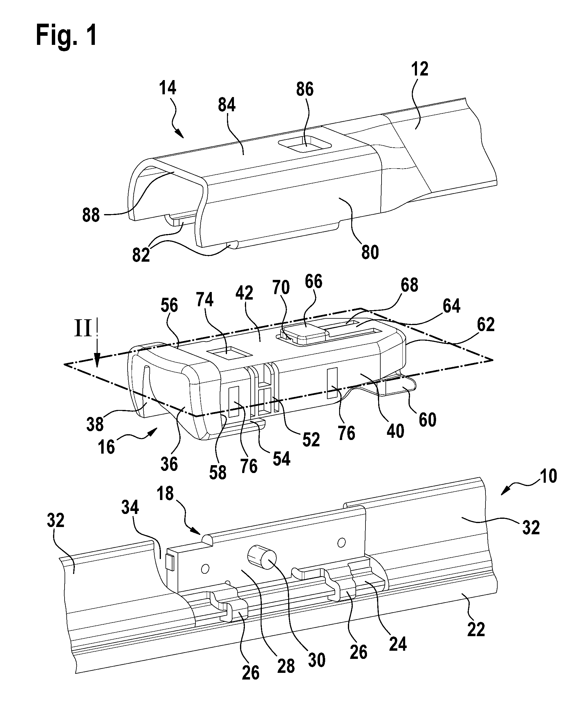
[0027]A wiper blade 10 of flat beam design comprises a wiper strip 20 having a wiper lip 22 and two spring rails serving as a support element 24, which are inserted in longitudinal grooves of the wiper strip 20. A connecting element 18 in the form of a sheet metal claw is fastened by means of claws 26 to the central section of parts of the supporting element 24 laterally protruding from said wiper strip 20. The claws 26 encompass the support element 26 along the outer longitudinal sides and are connected on their other end by a central web 28. Said web runs in the longitudinal direction of the wiper blade 10 and bears a hinge shaft 30 projecting on both sides thereof. Spoiler parts 32 are attached in the longitudinal direction to both sides of the connecting element 18. Said spoiler parts form between themselves a window 34 for said connecting element 18 and sit with guide profiles on the support element 24.

[0028]A connecting device, which comprises the connecting element 18, an ada...


PUM


Abstract

The invention relates to a connecting device which has a connecting element (18) of flat beam design fixed to a wiper blade (10) and an adapter (16) joined to said connecting element in an articulated manner, and also a joining element (14) that is joined to a wiper arm (12) and into the u-shaped cross-sectional profile of which the adapter (16) is inserted and, by means of a spring tongue (64) arranged on the top wall (42) thereof, is fixed to a pushbutton (66), the connecting element (18) having a central web (28) running in the longitudinal direction of the wiper blade (10) and bearing a hinge shaft (30) projecting on the long sides thereof, which is mounted in laterally flexible hubs (46) in side walls (40) of the adapter (16). According to the invention, the outwardly facing walls of the adapter (16), namely the side walls (40), the top wall (42), and the end walls (36, 62), have a general wall thickness of at least two millimeters, and the hubs (46) are to be formed as blind holes, the cylindrical surfaces of which form radial sliding surfaces (48) and the end faces of which form axial sliding surfaces (50), which are highly polished with an arithmetic mean roughness of Ra<0.2μ, and that the sliding surfaces (48, 50) be the sole contact surfaces between the connecting element (18) and the adapter (16).

Description

BACKGROUND OF THE INVENTION[0001]The invention relates to a connecting device for connecting a wiper blade to a wiper arm.[0002]A connecting device of the generic kind is known from the German patent publication DE 103 47 637 A1. A wiper blade of flat beam design is connected via said connecting device to a wiper arm in an articulated manner. The wiper blade comprises a wiper strip, in the longitudinal grooves of which two spring rails are laterally inserted, which serve as a support element and to which a connecting element in the form of a sheet metal claw is fastened. The connecting element comprises a central web which extends in the longitudinal direction of the wiper blade and which bears a hinge shaft that runs transversally thereto. Hubs of an adapter are mounted on the hinge shaft on both sides of the central web, wherein said hubs are arranged in spring tongues. Said hubs form laterally flexible parts of the side walls of the adapter. The spring tongues are separated from ...

Claims


Application Information

Patent Timeline
Patent Type & Authority Patents(United States)
IPC IPC(8): B60S1/40B60S1/38
CPCB60S1/3868B60S1/4038B60S1/3856B60S2001/3898B60S2001/4051B60S2001/4054B60S1/38B60S1/40
Inventor COART, KRISSAEVELS, PETERAZNAG, MOHAMEDWINDMOLDERS, ERICVERTONGEN, ROBERTBONROY, JAN
Owner ROBERT BOSCH GMBH
Why Eureka
Try Eureka