Supercharge Your Innovation With Domain-Expert AI Agents!

Systems and methods for dimming control with capacitive loads

a capacitive load and dimming control technology, applied in the field of integrated circuits, can solve the problems of low frequency oscillation, conventional light dimmer may not function properly, and significant challenges for leds to widely replace incandescent lamps, and achieve the effect of a broader range of applicability

Active Publication Date: 2015-01-27
ON BRIGHT ELECTRONICS SHANGHAI
View PDF27 Cites 54 Cited by
  • Summary
  • Abstract
  • Description
  • Claims
  • Application Information

AI Technical Summary

Benefits of technology

The solution stabilizes AC waveforms, reduces oscillations, and enhances system efficiency by minimizing resistor heating and energy consumption, ensuring proper operation even under varying voltage conditions.

Problems solved by technology

But, significant challenges remain for LEDs to widely replace incandescent lamps.
But such conventional light dimmer may not function properly when connected to capacitive loads, such as LEDs and / or associated circuits.
When the light dimmer starts conduction, internal inductance of the light dimmer and the capacitive loads may cause low frequency oscillation.
Hence, the Alternate Current (AC) waveforms of the light dimmer often becomes unstable, resulting in flickering, undesirable audible noise, and / or even damages to other system components. FIG. 1 shows simplified signal waveforms of a conventional light dimmer that is connected to capacitive loads.
But, for the light dimmer circuit 200, a current would flow through the resistor 240 even under normal working conditions, causing excessive heating of resistor and other system components.
Such heating often leads to low efficiency and high energy consumption.
But the system 400 still suffers from significant deficiencies.
Thus, the system 400 would not operate properly under these circumstances.

Method used


Image

  • Systems and methods for dimming control with capacitive loads
  • Systems and methods for dimming control with capacitive loads
  • Systems and methods for dimming control with capacitive loads

Examples


Embodiment Construction

[0029]The present invention is directed to integrated circuits. More particularly, the invention provides systems and methods for dimming control. Merely by way of example, the invention has been applied for dimming control using a light dimmer with capacitive loads. But it would be recognized that the invention has a much broader range of applicability.

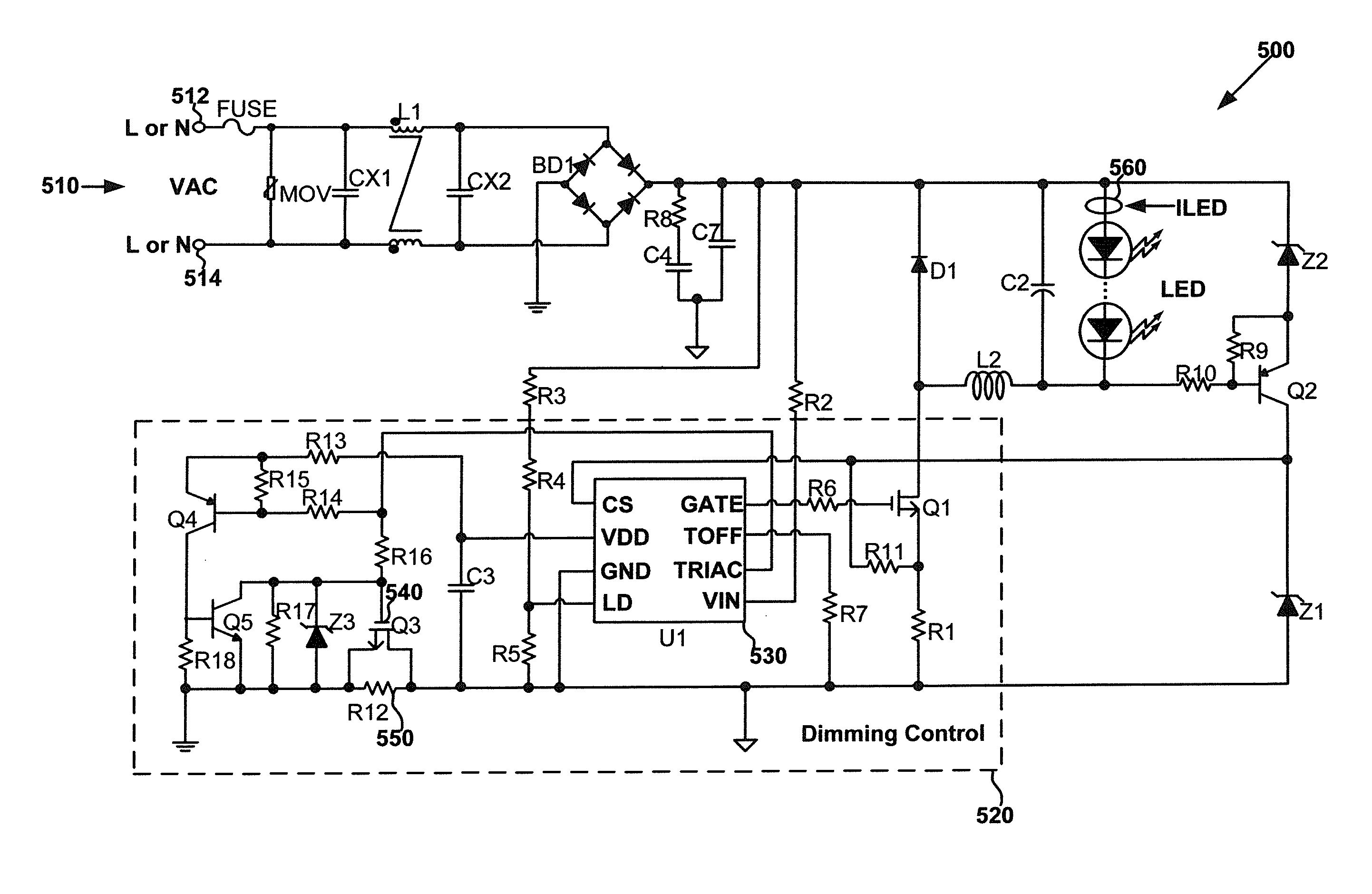
[0030]FIG. 5 is a simplified diagram showing a system for dimming control according to an embodiment of the present invention. This diagram is merely an example, which should not unduly limit the scope of the claims. One of ordinary skill in the art would recognize many variations, alternatives, and modifications. The system 500 includes at least input terminals 512 and 514, and a dimming control circuit 520. For example, the dimming control circuit 520 includes at least a system controller 530, a transistor 540, and a resistor 550.

[0031]According to one embodiment, a light dimmer (e.g., a TRIAC not shown in FIG. 5) sends an input si...


PUM


Abstract

System and method for dimming control. The system includes a system controller including a first controller terminal and a second controller terminal, a transistor including a first transistor terminal, a second transistor terminal and a third transistor terminal, and a resistor including a first resistor terminal and a second resistor terminal. The system controller is configured to generate a first signal at the first controller terminal based on an input signal and to generate a second signal at the second controller terminal based on the first signal. The first transistor terminal is coupled to the second controller terminal. The first resistor terminal is coupled to the second transistor terminal. The second resistor terminal is coupled to the third transistor terminal. The transistor is configured to receive the second signal at the first transistor terminal and to change between two conditions in response to the second signal.

Description

1. CROSS-REFERENCES TO RELATED APPLICATIONS[0001]This application claims priority to Chinese Patent Application No. 201110103130.4, filed Apr. 22, 2011, commonly assigned, incorporated by reference herein for all purposes.2. BACKGROUND OF THE INVENTION[0002]The present invention is directed to integrated circuits. More particularly, the invention provides systems and methods for dimming control. Merely by way of example, the invention has been applied for dimming control using a light dimmer with capacitive loads. But it would be recognized that the invention has a much broader range of applicability.[0003]Light emitting diodes (LEDs) have been widely used in various electronics applications, such as architectural lighting, automotive lighting, and backlighting of liquid crystal display (LCD). LEDs have been recognized to have significant advantages over other lighting sources, such as incandescent lamps, and the advantages include at least high efficiency and long lifetime. But, si...

Claims


Application Information

Patent Timeline
Patent Type & Authority Patents(United States)
IPC IPC(8): H05B37/02H05B44/00
CPCH05B33/0815H05B33/0851H05B45/10H05B45/375
Inventor ZHOU, JUNXIONG, ZHONGLIANGLI, MIAOCAO, YAMINGLUO, QIANGFANG, LIEYI
Owner ON BRIGHT ELECTRONICS SHANGHAI
Features
  • R&D
  • Intellectual Property
  • Life Sciences
  • Materials
  • Tech Scout
  • Unparalleled Data Quality
  • Higher Quality Content
  • 60% Fewer Hallucinations
Learn More