Supercharge Your Innovation With Domain-Expert AI Agents!

Transmit/receive switch

a technology of transmitting and receiving switch, applied in the direction of preventing transmission, electrical equipment, networks, etc., can solve the problems of slow energy loss, damage to these components, and rapid energy loss, so as to minimize the interdependence of design choices

Active Publication Date: 2015-02-03
QUALCOMM TECH INT
View PDF28 Cites 4 Cited by
  • Summary
  • Abstract
  • Description
  • Claims
  • Application Information

AI Technical Summary

Benefits of technology

The purpose of this invention is to decrease the joint effects of design options between receiving and transmitting equipment.

Problems solved by technology

A high Q means that energy is lost slowly whilst a low Q means that energy is lost quickly.
If the circuits were not isolated from each other during operation, damage could occur to these components.
This possibility of damage restricts the choice of possible LNA core devices and topology.
However, slow MOS devices are not preferred for LNA's that need to operate at high frequencies.

Method used


Image

  • Transmit/receive switch
  • Transmit/receive switch
  • Transmit/receive switch

Examples


Embodiment Construction

[0045]An embodiment of the present invention will now be discussed with reference to the figures. Features in the different embodiments that are labeled with the same reference numeral are equivalent to each other.

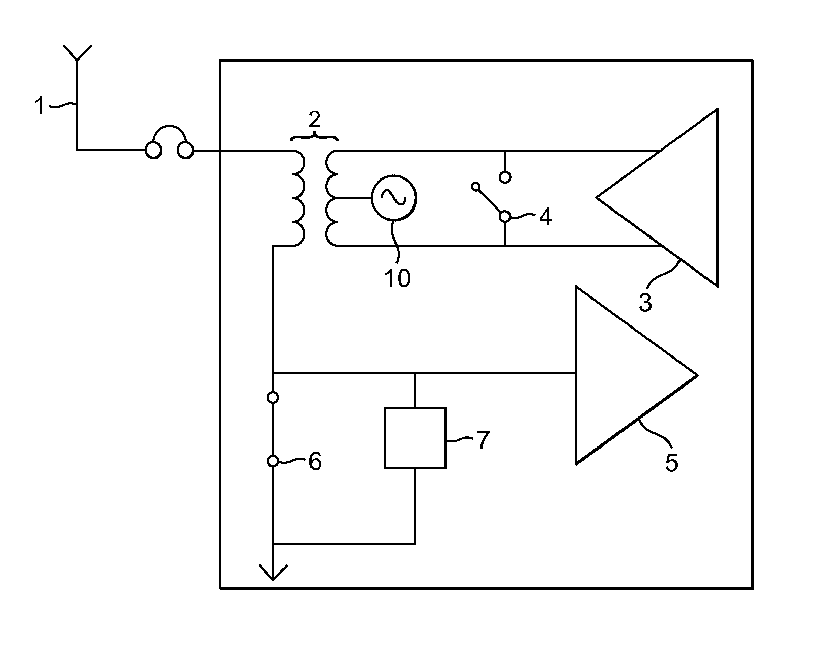
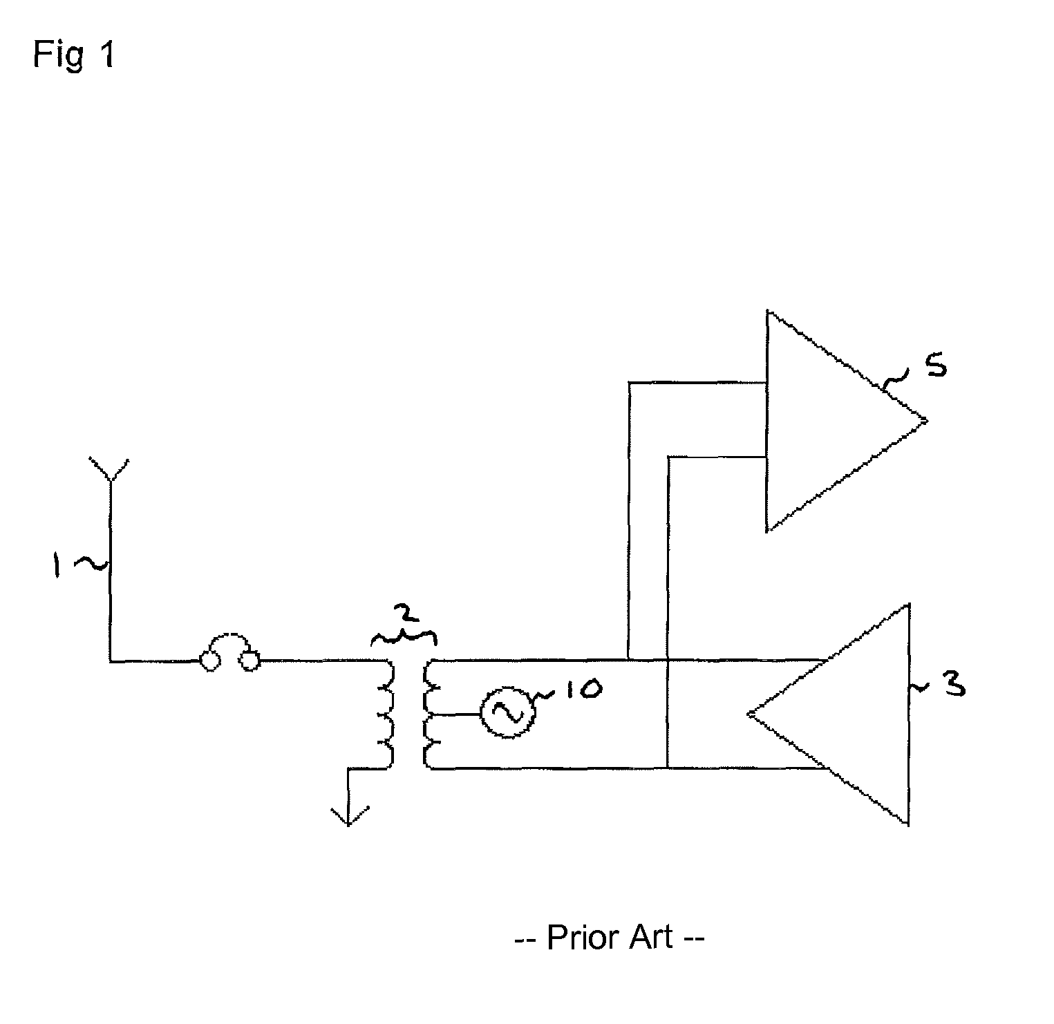
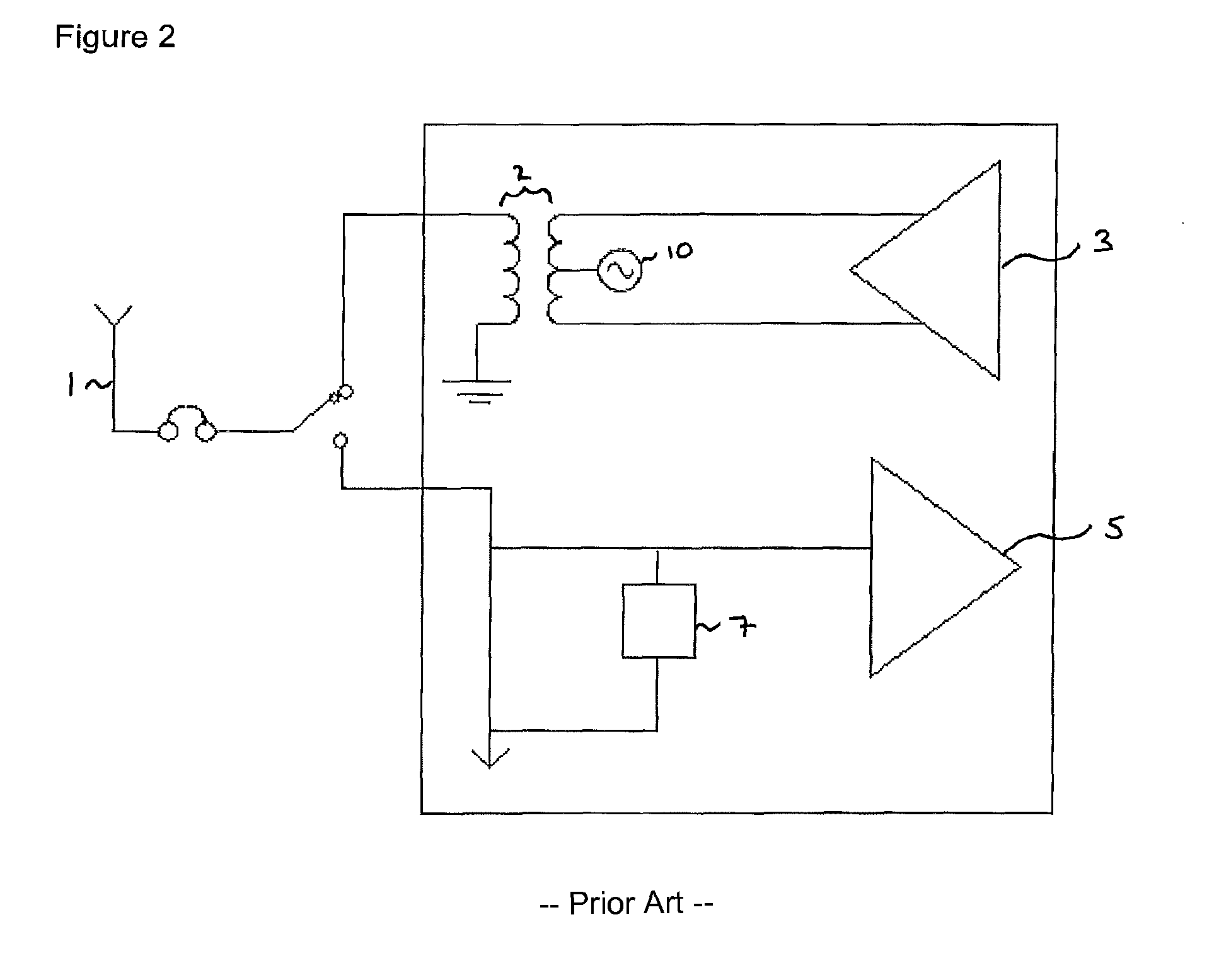
[0046]A transceiver typically comprises an antenna, receiving circuitry, transmitting circuitry and a balun. The receiving circuitry comprises an LNA. The transmitting circuitry comprises a PA. When the transceiver is transmitting, the transmitting circuitry is enabled and the receiving circuitry is disabled. When the transceiver is receiving, the receiving circuitry is enabled and the transmitting circuitry is disabled. The receiving circuitry is arranged such that the LNA is on the unbalanced side of the balun, along with the antenna. The transmitting circuitry is arranged such that the PA is on the balanced side of the balun.

[0047]The balun is chosen to match the design considerations of the PA. The PA can be a differential PA.

[0048]The LNA can be a single-ended LNA. Al...


PUM


Abstract

A transceiver includes a first circuit having a connector for connection to an antenna and receiving circuitry, and a second circuit having transmitting circuitry. The first and second circuits are coupled using a balun, where the balun is arranged so that its unbalanced side is in the first circuit and its balanced side is in the second circuit.

Description

CLAIM OF FOREIGN PRIORITY[0001]This application claims priority under 35 U.S.C. §119 from Application No. GB1019515.4 filed in the United Kingdom on Nov. 18, 2010, the contents of which are incorporated by reference herein in their entirety.BACKGROUND OF THE INVENTION[0002]A balun is a circuit component frequently used to connect together sections of different impedances. A balun is essentially a transformer connecting first and second circuits that generates a signal in a first circuit based on the signal in a second circuit. More particularly, a balun can convert a signal that is symmetrical (or “balanced”) about ground to a signal that is asymmetrical (or “unbalanced”) about ground and vice versa.[0003]In a transceiver, transmitting and receiving circuitry are commonly arranged to receive a differential input from a balun whilst the antenna is arranged on the unbalanced side. This means that the choice of balun and of the various components used in the two types of circuitry is m...

Claims


Application Information

Patent Timeline
Patent Type & Authority Patents(United States)
IPC IPC(8): H04B1/44H04B1/48
CPCH04B1/48H03H7/42H04B1/581
Inventor KWOK, TERENCE CHI-FUNGNEWTON, TIMOTHYCHANG, SIMON
Owner QUALCOMM TECH INT
Features
  • R&D
  • Intellectual Property
  • Life Sciences
  • Materials
  • Tech Scout
  • Unparalleled Data Quality
  • Higher Quality Content
  • 60% Fewer Hallucinations
Learn More