Storage and recovery of thermal energy based on counter current principle of heat transfer medium transportation

a technology of heat transfer medium and storage energy, which is applied in the direction of indirect heat exchangers, machines/engines, lighting and heating apparatus, etc., can solve the problems of complex mechanical arrangement of system components and known system inflexibility, and achieve the effect of high-efficiency conversion of recovered thermal energy, direct consumption, and easy feeding

Active Publication Date: 2015-03-03
SIEMENS GAMESA RENEWABLE ENERGY AS
View PDF18 Cites 10 Cited by
  • Summary
  • Abstract
  • Description
  • Claims
  • Application Information

AI Technical Summary

Benefits of technology

[0012]By using the above described counter current principle, when energy is recovered from the thermal energy storage device, it is possible to heat up the cold heat transfer medium to nearly the same temperature as the inlet temperature of the hot heat transfer medium when thermal energy is inserted into the thermal energy storage device. In this way, if the hot heat transfer medium comprises heated steam, the heated up (originally) cold heat transfer medium may also comprise heated steam which then may be used directly to drive a steam turbine without any further heating means. Thereby, the efficiency of the heat storage process can be significantly increased.
[0038]Thereby, a rotating shaft of the steam turbine may be connected to an electric power generator, which is capable of converting the mechanical energy being provided by the steam turbine into electric energy, which can be easily fed to a utility grid and / or which can be directly consumed by at least one electric consumer.

Problems solved by technology

One disadvantage of this wind-powered energy production and storing system is that there is a direct mechanical connection between the energy storing system and the wind turbine and that all the energy storage equipment, besides the storing stations, is placed in the wind turbine resulting in a complex mechanical arrangement of the system components.
This causes the known system to be not flexible.

Method used


Image

  • Storage and recovery of thermal energy based on counter current principle of heat transfer medium transportation
  • Storage and recovery of thermal energy based on counter current principle of heat transfer medium transportation
  • Storage and recovery of thermal energy based on counter current principle of heat transfer medium transportation

Examples


first embodiment

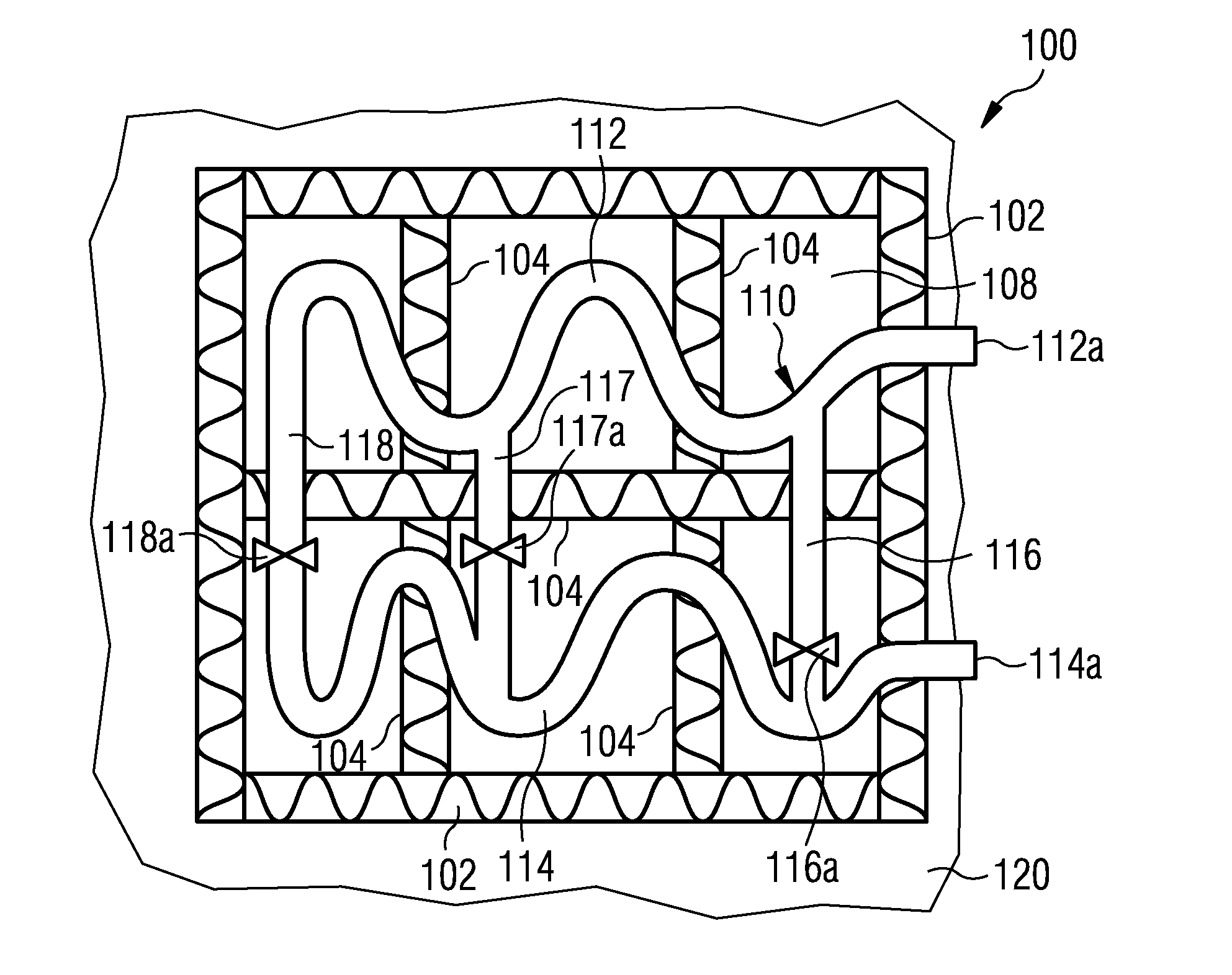
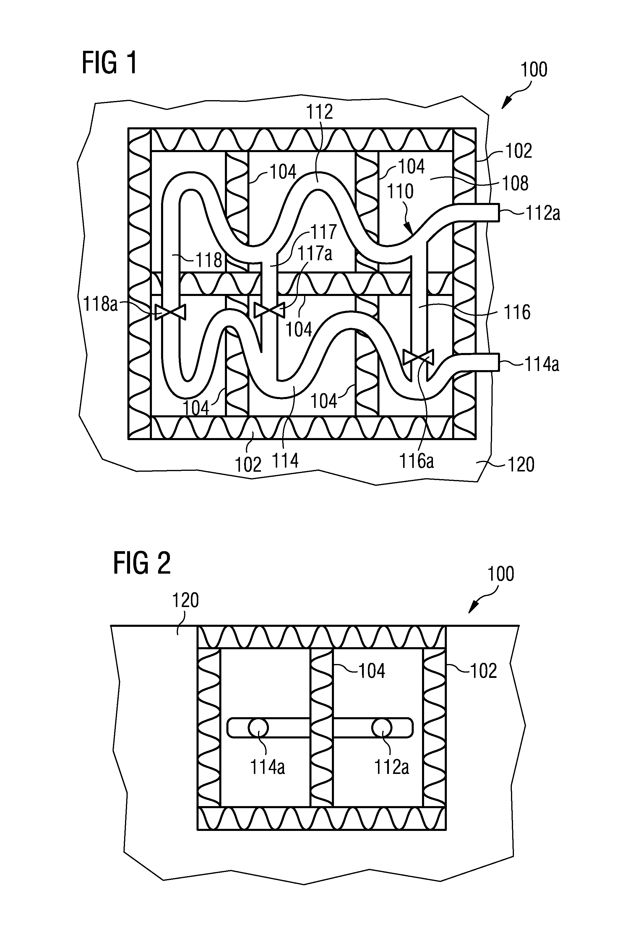
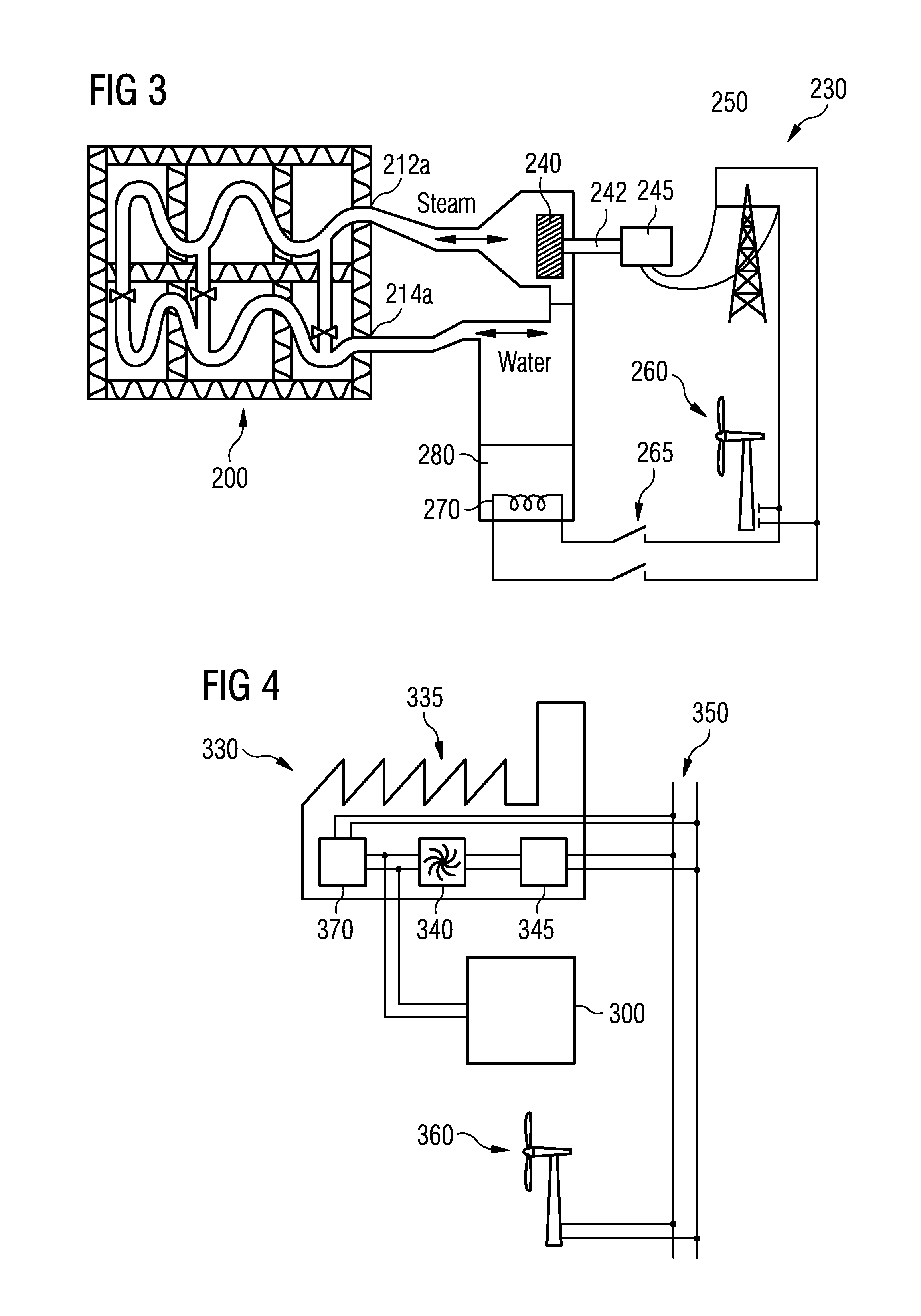
[0064]FIG. 3 shows a schematic illustration of a thermal energy storing and recovering system 230 in accordance with the invention. According to the embodiment described here water respectively (water) steam is used as a heat transfer medium.

[0065]To recover stored energy water is fed into a thermal energy storage device 200 e.g. by means of a not depicted a pumping device through a second end 214a of a heat exchanger arrangement of the thermal energy storage device 200. As a result, steam is coming out of a first end 212a of the heat exchanger arrangement. Thereby, the above described counter current principle is employed, i.e. the flow direction of the water / steam when recovering energy is opposite compared to the flow direction of the water / steam when the thermal energy storage device 200 is charged.

[0066]The out coming steam is fed into a steam turbine 240 which drives an electric power generator 245 through a shaft connection 242. The steam in the steam turbine 240 may be overh...

second embodiment

[0069]FIG. 4 shows schematic illustration of a thermal energy storing and recovering system 330 in accordance with the invention. In this embodiment, a thermal power generation plant 335 is connected to a utility grid 350 and to a thermal energy storage device 300. According to the embodiment described here the power generation plant 335 comprises a steam turbine 340 with a condenser (not shown) and a connected electrical power generator 345 and an electrical boiler 370. Again, the electrical boiler 370 may be replaced or may be supplemented by means of a heat pump system or other heating means.

[0070]The thermal power generation plant 335 is connected to the thermal energy storage device 300 both for energy storage and for recovering of stored energy as explained above with reference to FIG. 3. Also here a wind turbine 360 or other kind of alternative energy resources may be connected to the utility grid 3540.

[0071]FIG. 5 illustrates an exemplary temperature profile along a pipe of ...

third embodiment

[0076]FIG. 7 shows a schematic illustration of a thermal energy storing and recovering system 630 in accordance with the invention. Thereby, charging of a thermal energy storage device 600 is performed by means of a heat pump 670 and a discharging of the thermal energy storage device is performed by means of a heat engine 690.

[0077]As can be seen from FIG. 7, the heat engine 690 comprises an evaporator 684, which receive thermal energy from the thermal energy storage device 600. Further, the heat engine 690 comprises a steam turbine 640, which is connected down-stream with respect to the evaporator 684. The steam turbine 640 may be connected in a known manner with a not depicted electric generator for converting mechanical energy provided by the steam turbine 640 into electric energy. Furthermore, the heat engine 690 comprises a feed pump 682 which conveys condensed water to the evaporator 684. According to the embodiment described here the heat engine 690 is operated with the well ...


PUM


Abstract

A thermal energy storage device is provided. The device has a heat exchanger arrangement for guiding a flow of a heat transfer medium between a first end and a second end of the heat exchanger arrangement, and a heat storage material surrounding the heat exchanger arrangement. The heat exchanger arrangement transports the heat transfer medium from the first end to the second end if the thermal energy storage device is in a first operational mode, in which the heat storage material is supposed to receive thermal energy from the heat transfer medium, and transports the heat transfer medium from the second end to the first end if the thermal energy storage device is in a second operational mode, in which the heat storage material is supposed to release thermal energy to the heat transfer medium.

Description

CROSS REFERENCE TO RELATED APPLICATIONS[0001]This application is the U.S. National Stage of International Application No. PCT / EP2010 / 066526 filed Oct. 29, 2010 and claims the benefit thereof. The International Application claims the benefits of the European application No. 10007149.7 filed Jul. 12, 2010, both of the applications are incorporated by reference herein in their entirety.FIELD OF INVENTION[0002]The present invention relates to the field of temporarily storing thermal energy. In particular, the present invention relates to a thermal energy storage device comprising a heat exchanger arrangement and a heat storage material. Further, the present invention relates to a thermal energy storing and recovering system comprising such a thermal energy storage device and to a method for operating such a thermal energy storage device.ART BACKGROUND[0003]The production of electric power from various types of alternative energy sources such as for instance wind turbines, solar power pl...

Claims


Application Information

Patent Timeline
Patent Type & Authority Patents(United States)
IPC IPC(8): F01K1/00F28D17/02F01K3/00F01K3/18F28D17/04F28D20/00F28F27/02
CPCF28D17/04F28D20/00F28D20/0056F28F27/02F01K3/004F01K3/186Y02E60/142Y02E60/14
Inventor STIESDAL, HENRIK
Owner SIEMENS GAMESA RENEWABLE ENERGY AS
Why Eureka
Try Eureka