Intermediate hopper and image forming apparatus

a technology of image forming apparatus and hopper, which is applied in the direction of electrographic process apparatus, instruments, optics, etc., can solve the problems of inability to supply toner to the developing device, inability to accurately detect the presence or absence of toner, and inability to prevent the production of toner, so as to prevent the false detection of toner, and accurately detect the presence or absence of toner

Active Publication Date: 2015-03-03
SHARP KK
View PDF17 Cites 1 Cited by
  • Summary
  • Abstract
  • Description
  • Claims
  • Application Information

AI Technical Summary

Benefits of technology

[0019]Since the agitation plate is provided at a position facing the toner receiving port, and the toner amount detection sensor is provided on an upstream side relative to the agitation plate, the toner supplied through the toner receiving port is temporarily accumulated, and the toner amount detection sensor detects the toner accumulated without a gap. According to the configuration, therefore, it is possible to accurately detect presence or absence of the toner and to prevent false detection of the toner in the intermediate hopper.
[0020]In addition, since it is possible to accurately detect presence or absence of the toner, toner bridging, which occurs around the toner receiving port due to false detection of toner in a conventional hopper, is prevented, and therefore the toner can be supplied to the developing device without failure.

Problems solved by technology

While being able to discharge some of the toner being circulated and carried inside the container tank swiftly by using the two carrying screws, the conventional intermediate toner hopper as described above is disadvantageous in that the toner stays at an end of the container tank, because the two carrying screws do not have a partition therebetween.
Due to the toner bridging, disadvantageously, the toner cannot be supplied to the developing device, prevented from being carried normally in the intermediate toner hopper.
The toner thus supplied unsteadily and nonuniformly may cause an uneven image.

Method used


Image

  • Intermediate hopper and image forming apparatus
  • Intermediate hopper and image forming apparatus
  • Intermediate hopper and image forming apparatus

Examples


Embodiment Construction

[0034]The present invention provides an intermediate hopper that prevents false detection of toner in the intermediate hopper and allows steady supply of toner to a developing device even when supply of toner from a toner cartridge (toner supplying device) is not sufficient during replacement of the toner cartridge, and an image forming apparatus including the intermediate hopper.

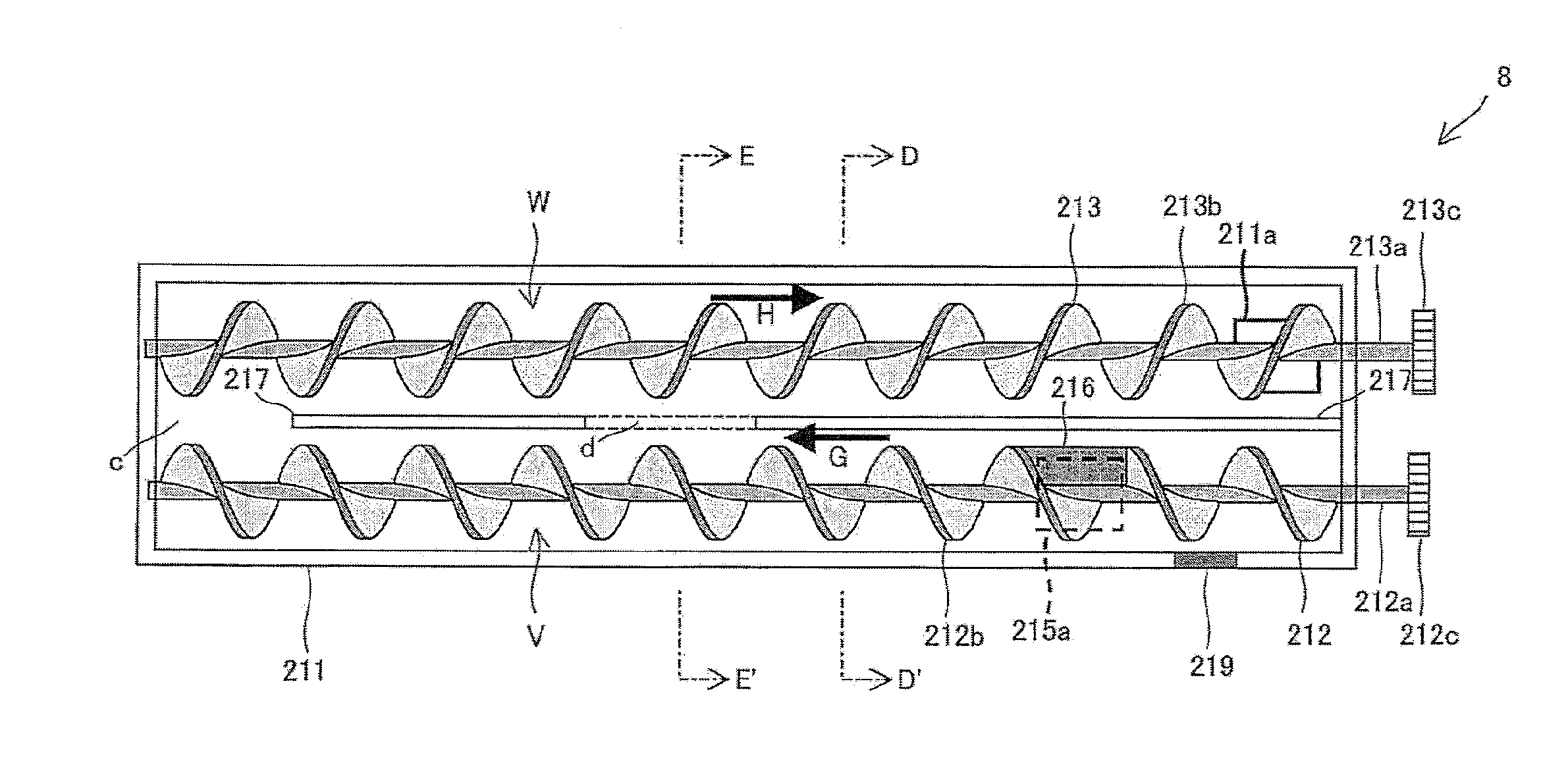
[0035]In the intermediate hopper of this invention, the partition comprises an intermediate slit for guiding the toner contained in the first toner conveyance path to the second toner conveyance path.

[0036]According to the configuration, even when a toner-missing space is generated in any of the toner conveyance paths of the intermediate hopper while a toner supplying device is being replaced without suspending an image formation process, for example, toner can be supplied to the toner-missing space through the intermediate slit provided to the partition separating the first and second toner conveyance path...


PUM


Abstract

An intermediate hopper has a toner reception tub, a partition for dividing an internal space of the toner reception tub; a first and a second toner conveyance path; a first toner conveyance screw being provided in the first toner conveyance path; a second toner conveyance screw being provided in the second toner conveyance path; a toner receiving port for receiving the toner; a toner communicating path for guiding the toner in the first toner conveyance path to the second toner conveyance path; a toner discharge port; and a toner amount detection sensor, wherein the first toner conveyance screw further comprises an agitation plate disposed at a position facing the toner receiving port so as to extend radially from the first rotation axis and fixed in parallel with the first rotation axis, and the toner amount detection sensor is provided on an upstream side relative to the agitation plate.

Description

CROSS-REFERENCE TO RELATED APPLICATIONS[0001]This application is related to Japanese application No. 2012-020891 filed on 2 Feb. 2012 whose priority is claimed under 35 USC §119, the disclosure of which is incorporated by reference in its entirety.BACKGROUND OF THE INVENTION[0002]1. Field of the Invention[0003]The present invention relates to an intermediate hopper and an image forming apparatus. More particularly, the present invention relates to an intermediate hopper for temporarily containing toner to be supplied to a developing device and an image forming apparatus such as an electrostatic copying machine, a laser printer and a facsimile machine that forms images by an electrophotographic method by guiding the toner contained in the intermediate hopper to the developing device.[0004]2. Description of the Related Art[0005]In the image forming apparatus using the electrophotographic method, an electrostatic latent image is formed on a surface of a photoconductor drum (toner image...

Claims


Application Information

Patent Timeline
Patent Type & Authority Patents(United States)
IPC IPC(8): G03G15/08
CPCG03G15/0822G03G15/0893G03G15/0877
Inventor AKEDO, SHUICHI
Owner SHARP KK
Why Eureka
Try Eureka