Hydraulic control device and abnormality determination method for the same

a technology of abnormality determination and hydraulic control device, which is applied in the direction of fluid couplings, rotary clutches, couplings, etc., can solve the problem of insufficient justification, and achieve the effect of accurately determining the presence or absen

Inactive Publication Date: 2014-10-09
AISIN AW CO LTD
View PDF2 Cites 0 Cited by
  • Summary
  • Abstract
  • Description
  • Claims
  • Application Information

AI Technical Summary

Benefits of technology

[0005]It is therefore a main object of the hydraulic control device and the abnormality determination method for the hydraulic control device according to the present invention to make it possible to determine the presence or absence of an abnormality of a pressure regulation valve involved in shifting during a change between shift speeds.
[0022]According to the method, it is possible to accurately determine the presence or absence of an abnormality of the disengagement-side pressure regulation valve involved in shifting during a change between shift speeds.

Problems solved by technology

In order to secure further safety by more quickly determining the presence or absence of an abnormality of a pressure regulation valve such as a solenoid valve according to Patent Document 1, however, it is not sufficient to just determine the presence or absence of an abnormality of a pressure regulation valve not involved in shifting during a change between shift speeds, and it is desired to determine the presence or absence of an abnormality of a pressure regulation valve involved in shifting during a change between shift speeds.

Method used


Image

  • Hydraulic control device and abnormality determination method for the same
  • Hydraulic control device and abnormality determination method for the same
  • Hydraulic control device and abnormality determination method for the same

Examples


Embodiment Construction

[0031]Now, an embodiment of the present invention will be described below.

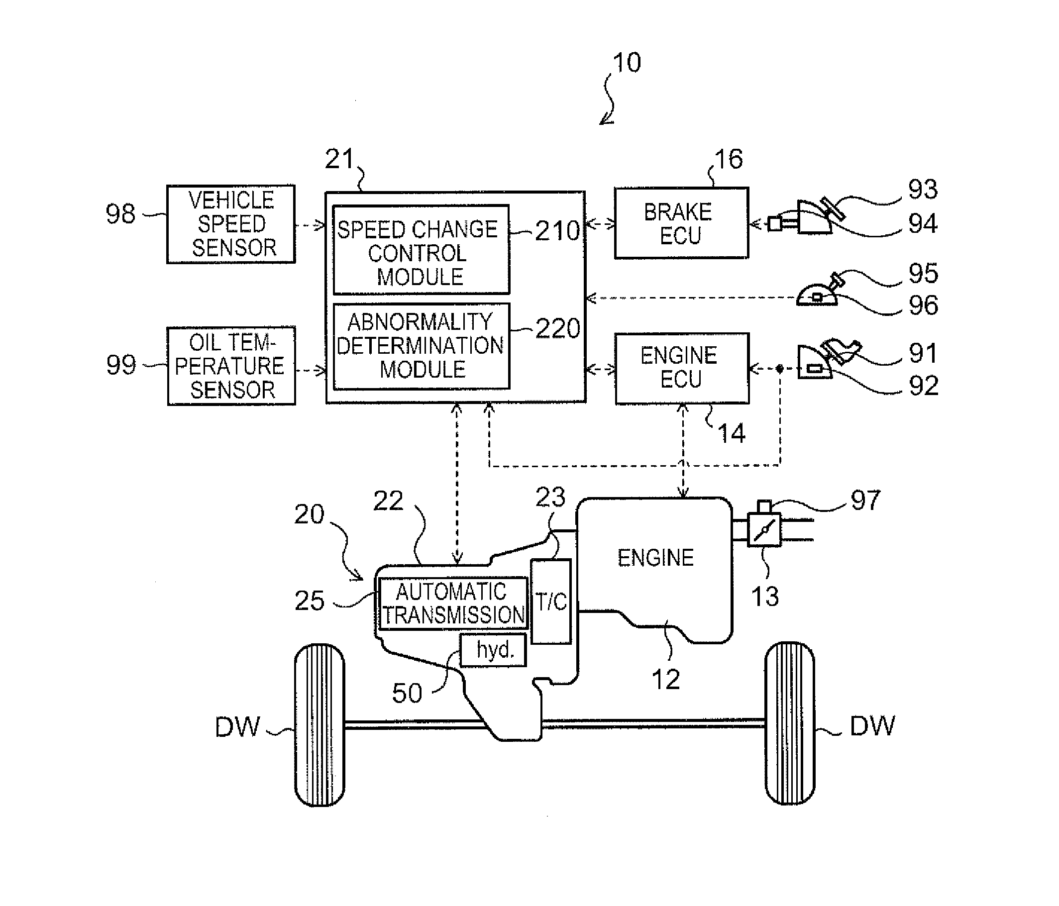
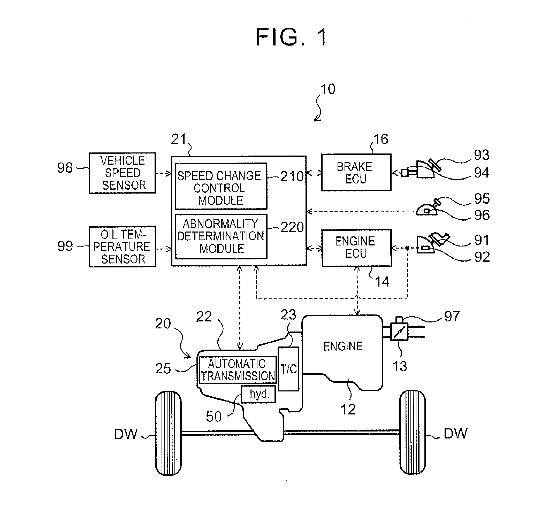
[0032]FIG. 1 illustrates a schematic configuration of an automobile 10 which is a vehicle incorporating a hydraulic control device 50 according to the present invention. The automobile 10 illustrated in the drawing includes an engine 12 serving as a power source which is an internal combustion engine that outputs power through explosive combustion of a mixture of a hydrocarbon fuel, such as gasoline and light oil, and air, an engine electronic control unit (hereinafter referred to as an “engine ECU”) 14 that controls the engine 12, a brake electronic control unit (hereinafter referred to as a “brake ECU”) 16 that controls an electronically controlled hydraulic brake unit (not illustrated), a power transfer device 20 connected to a crankshaft of the engine 12 to transfer power from the engine 12 to left and right drive wheels DW, and so forth. The power transfer device 20 has a torque converter 23, a stepped au...


PUM


Abstract

A hydraulic control device that controls a hydraulic pressure for a plurality of friction engagement elements included in an automatic transmission mounted on a vehicle to establish a plurality of shift speeds, including: a plurality of pressure regulation valves, a plurality of hydraulic switches, speed change control means, and abnormality determination means.

Description

TECHNICAL FIELD[0001]The present invention relates to a hydraulic control device that controls a hydraulic pressure for a plurality of friction engagement elements included in an automatic transmission mounted on a vehicle to establish a plurality of shift speeds, and to an abnormality determination method for the hydraulic control device.BACKGROUND ART[0002]Hitherto, there has been known a hydraulic control device of this type in which an output command value is output to a solenoid valve to directly control a working hydraulic pressure for a friction engagement element corresponding to the solenoid valve (see Patent Document 1, for example). The hydraulic control device includes detection means for outputting a signal when a hydraulic pressure within an oil passage that connects between the solenoid valve and the friction engagement element corresponding to the solenoid valve reaches a pressure determined in advance, determination means for determining whether or not the hydraulic...

Claims


Application Information

Patent Timeline
Patent Type & Authority Applications(United States)
IPC IPC(8): F16D35/00
CPCF16D35/00F16H61/12F16H61/686F16H2059/683F16H2061/1212
Inventor JINNO, TOMOYATASHIRO, MUNEHIROYAMAGUCHI, MASAMICHISHIMIZU, TETSUYAISHIKAWA, KAZUNORI
Owner AISIN AW CO LTD
Why Eureka
Try Eureka