Method and system for diagnosing abnormality of hydraulic device

a hydraulic device and abnormality diagnosis technology, applied in the direction of pump parameters, servometer circuits, pump control, etc., can solve the problems of difficult to monitor all of these parameters, and difficult to detect the decrease in output, so as to accurately diagnose the presence of abnormality

Active Publication Date: 2021-11-23
MITSUBISHI HEAVY IND LTD
View PDF7 Cites 0 Cited by
  • Summary
  • Abstract
  • Description
  • Claims
  • Application Information

AI Technical Summary

Benefits of technology

[0028]According to at least one embodiment of the present invention, it is possible to provide the abnormality diagnosis method for the hydraulic device and the abnormality diagnos

Problems solved by technology

In an actual hydraulic device, however, it is difficult to monitor all of these parameters because of restrictions in terms of cost and layout.
In addition, it is difficult to detect the decrease in output just by directly measuring the leakage amount of the working oil used for the hydraulic device and the fric

Method used


Image

  • Method and system for diagnosing abnormality of hydraulic device
  • Method and system for diagnosing abnormality of hydraulic device
  • Method and system for diagnosing abnormality of hydraulic device

Examples


first embodiment

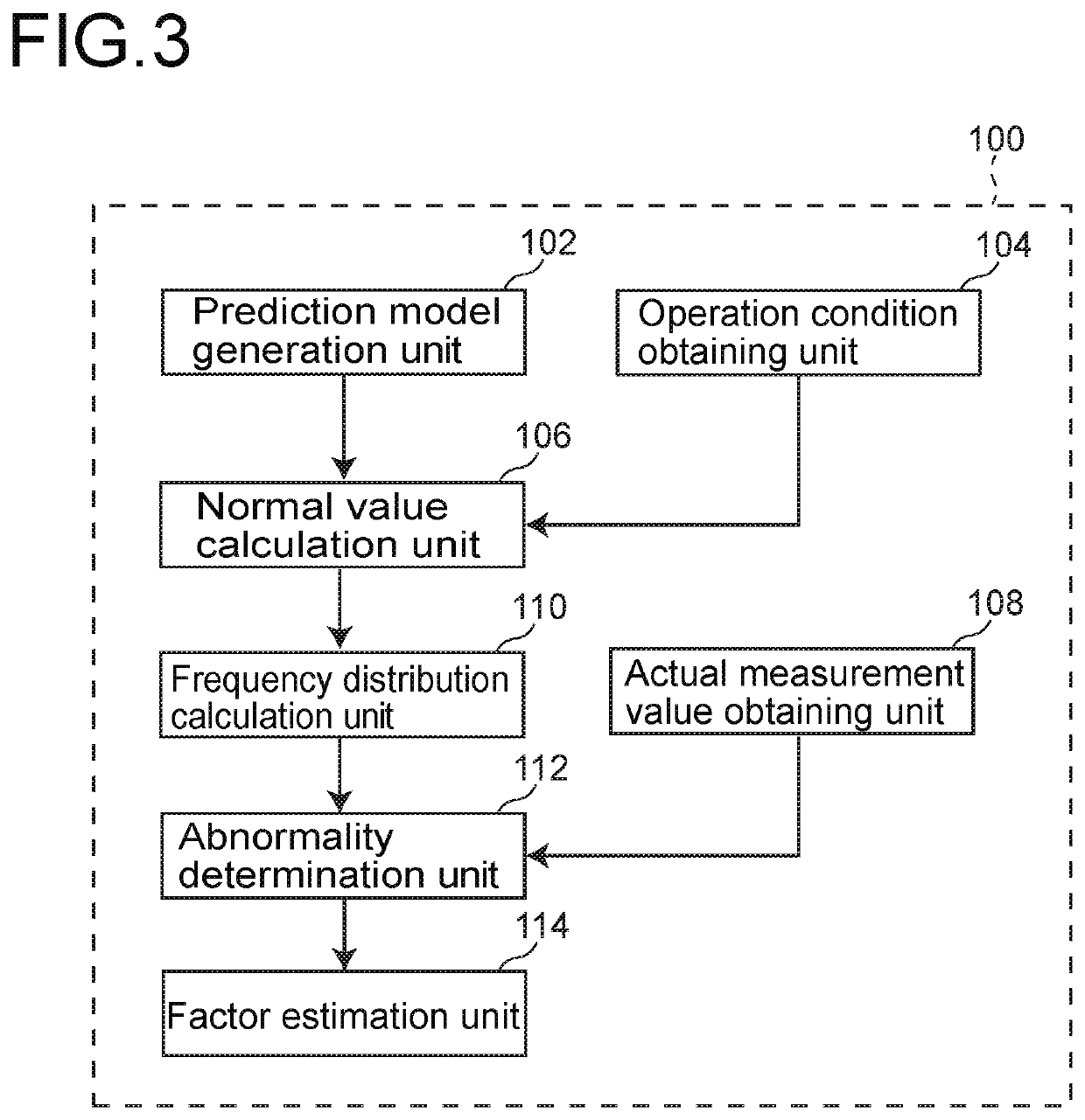
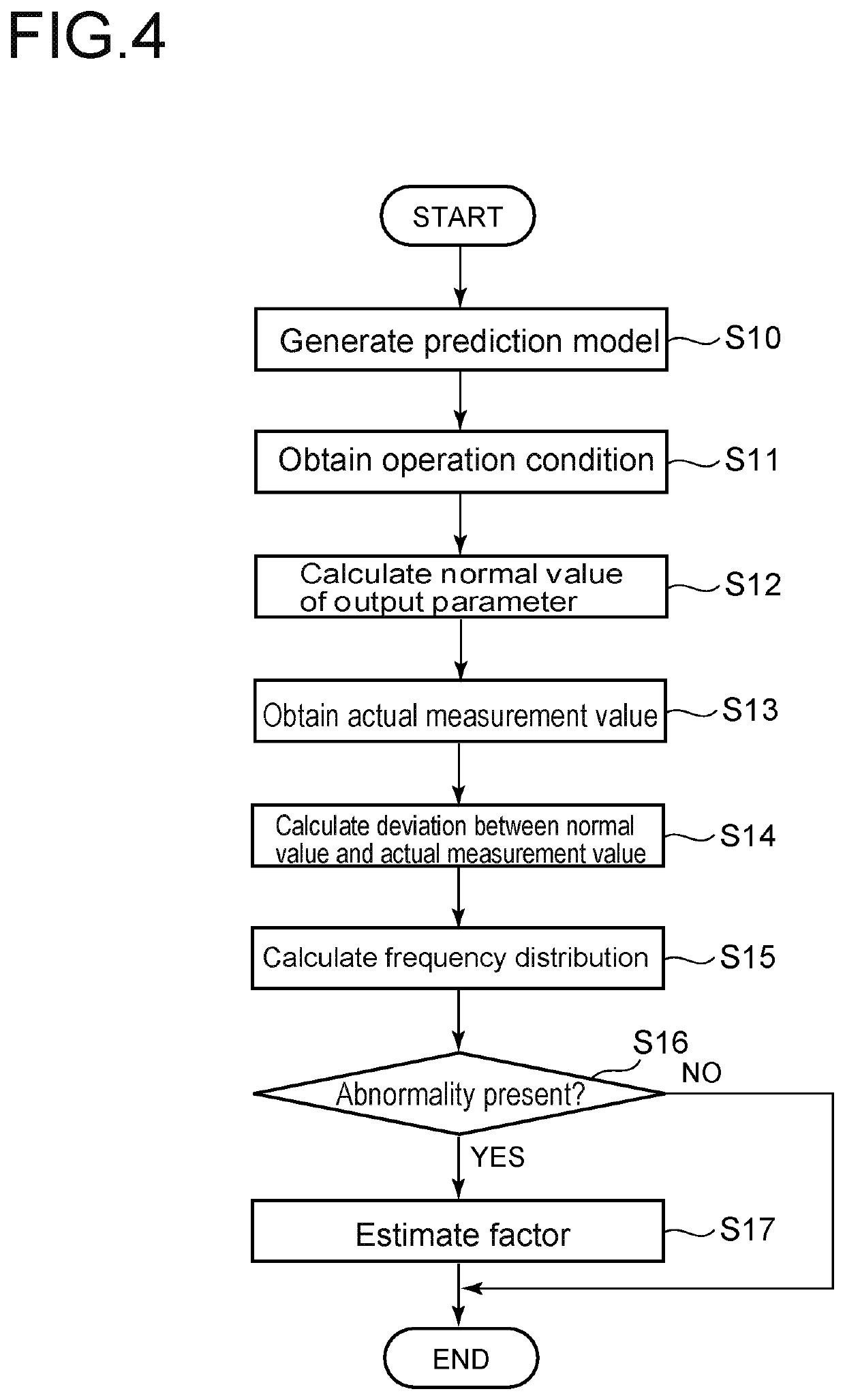
[0060]FIG. 3 is a block diagram of the configuration of an abnormality diagnosis system 100 according to the first embodiment. FIG. 4 is a flowchart showing steps of the abnormality diagnosis method performed by the abnormality diagnosis system 100 in FIG. 3.

[0061]As shown in FIG. 3, the abnormality diagnosis system 100 includes a prediction model generation unit 102, an operation condition obtaining unit 104, a normal value calculation unit 106, an actual measurement value obtaining unit 108, a frequency distribution calculation unit 110, an abnormality determination unit 112, and a factor estimation unit 114.

[0062]The abnormality diagnosis system 100 is configured by installing a program for performing the abnormality diagnosis method according to at least one embodiment of the present invention on a computation processing device such as a computer. In this case, the program may be stored in a computer-readable storage medium in advance or may be installed by reading the storage m...

second embodiment

[0102]Next, an abnormality diagnosis system 200 and an abnormality diagnosis method performed by the abnormality diagnosis system 200 according to the second embodiment will be described. FIG. 11 is a block diagram of the configuration of the abnormality diagnosis system 200. FIG. 12 is a flowchart showing steps of the abnormality diagnosis method performed by the abnormality diagnosis system 200 in FIG. 11.

[0103]As shown in FIG. 11, the abnormality diagnosis system 200 includes a physical model generation unit 202, an operation condition obtaining unit 204, an output parameter calculation unit 206, an abnormality determination unit 208, and a factor estimation unit 210.

[0104]The abnormality diagnosis system 200 is configured by installing a program for performing the abnormality diagnosis method according to at least one embodiment of the present invention on a computation processing device such as a computer. In this case, the program may be stored in a computer-readable storage m...


PUM


Abstract

An abnormality diagnosis method is targeted at a hydraulic device which includes a hydraulic pump and a driven device driven by the hydraulic pump. The method includes calculating a frequency distribution with regard to a deviation between a normal value of an output parameter corresponding to an operation condition and an actual measurement value of the output parameter using a prediction model, and determining the presence of an abnormality if an average of the deviation exceeds a threshold. If the presence of the abnormality is determined, a factor of the abnormality is estimated based on the range of the deviation where a waveform peak of the frequency distribution exists.

Description

TECHNICAL FIELD[0001]The present disclosure relates to an abnormality diagnosis method for a hydraulic device including a hydraulic pump and an abnormality diagnosis system for the hydraulic device.BACKGROUND ART[0002]A hydraulic device which uses oil as an operation medium is known. The hydraulic device of this type may include a hydraulic pump which produces pressurized oil by power input from a power source such as an engine, electric motor, or the like and a driven device which is driven by the pressurized oil produced by the hydraulic pump. As such a hydraulic device, there is a hydrostatic transmission (HST) including a hydraulic motor as a driven device.[0003]As the hydraulic pump used for the hydraulic device, JPH9-256945A discloses an axial-piston hydraulic pump. The axial-piston hydraulic pump includes a cylinder block with a plurality of cylinders. When the cylinder block rotates by power from a power source, a plurality of pistons disposed in the respective cylinders rec...

Claims


Application Information

Patent Timeline
IPC IPC(8): F15B19/00F15B20/00F04B49/10
CPCF15B19/005F04B49/10F15B19/007F15B20/00F04B2201/12F15B7/006F15B7/008F15B2211/20561F15B2211/20546F15B2211/27F15B2211/6343F15B2211/7058F15B2211/6336F15B2211/8633F15B2211/633F15B2211/6333F04B51/00
Inventor HAYASHI, TOSHIKAZUKUBO, HIROYOSHIYUGE, ATSUSHIHAYASHI, KENTARO
Owner MITSUBISHI HEAVY IND LTD
Why Eureka
Try Eureka