
LED mounting circuit board, belt-like flexible LED light and LED illuminating device using the same

a technology of led illuminating device and mounting circuit board, which is applied in the direction of lighting support device, lighting and heating apparatus, light source combination, etc., can solve the problems of inability to meet various customer needs, difficult to carry out curving in a perpendicular direction, and inability to carry out bending in the transverse direction, etc., to achieve the effect of increasing the light rang

Active Publication Date: 2015-03-17
ATEX CO LTD
View PDF27 Cites 6 Cited by
  • Summary
  • Abstract
  • Description
  • Claims
  • Application Information

AI Technical Summary

Benefits of technology

The present invention aims to provide a flexible LED light that can be bent in multiple directions, is long and compact, applies minimal stress to the circuit board, and is waterproof. The LED light uses a conventional surface mounting type LED, which makes it easy to find and use. The invention also provides a circuit board that can implement this flexible LED light. Additionally, an LED illuminating device is also provided to demonstrate the versatility of the invention.

Problems solved by technology

To the contrary, with this structure, it is hard to carry out curving in a perpendicular direction (a transverse direction of the belt-like FPC) to the LED light emitting direction until the belt-like light emitting module is twisted.
Thus, it is impossible to carry out bending in the transverse direction.
Since the lateral light emitting LED or the shell type LED is used for special applications, however, a luminance or a type of a luminescent color is poor so that various customer needs cannot be satisfied.
Thus, a mass production has problems.
For this reason, there is a problem in that a part of a light irradiated from the LED is intercepted by the circuit board body when the LED is lower than the circuit board body.
For this reason, there is a problem in that a stress is applied to the circuit board in use with bending.

Method used


Image

  • LED mounting circuit board, belt-like flexible LED light and LED illuminating device using the same
  • LED mounting circuit board, belt-like flexible LED light and LED illuminating device using the same
  • LED mounting circuit board, belt-like flexible LED light and LED illuminating device using the same

Examples


first embodiment

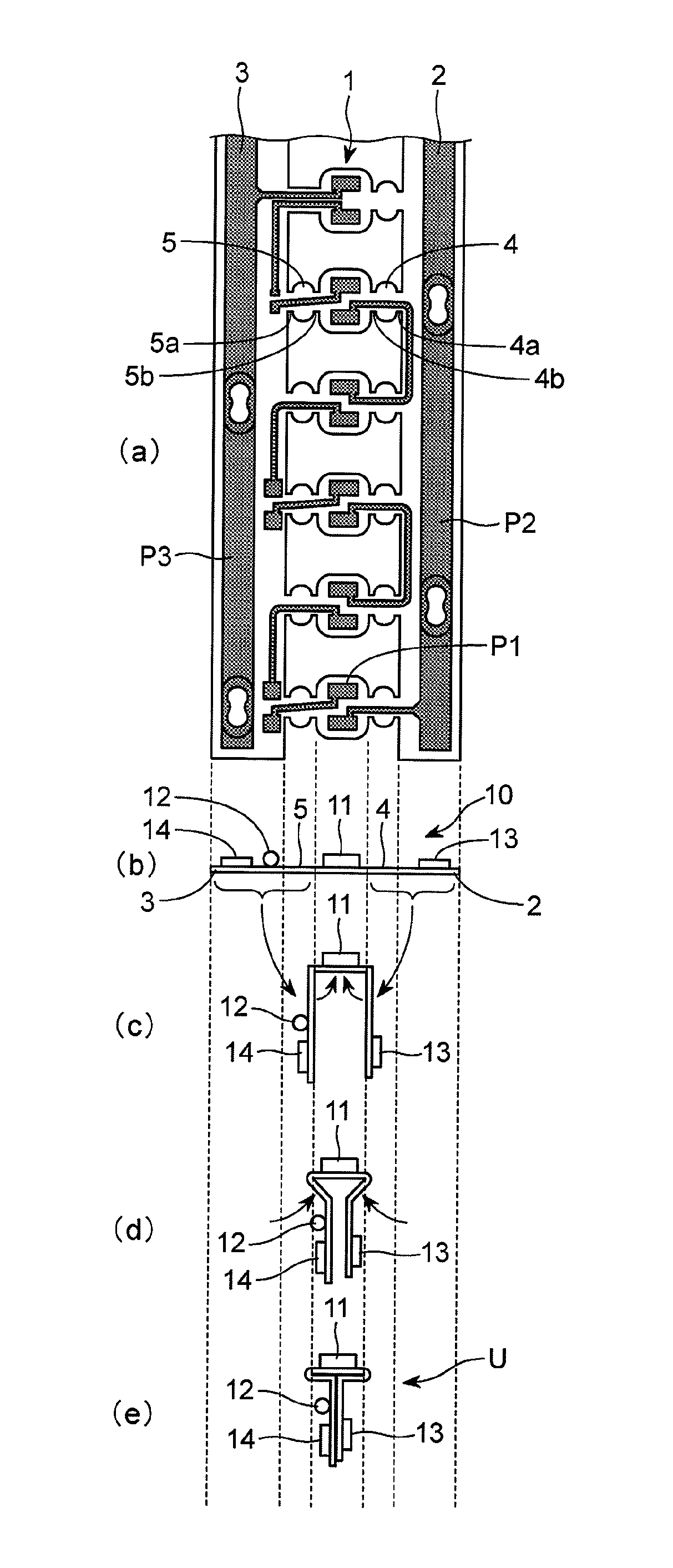
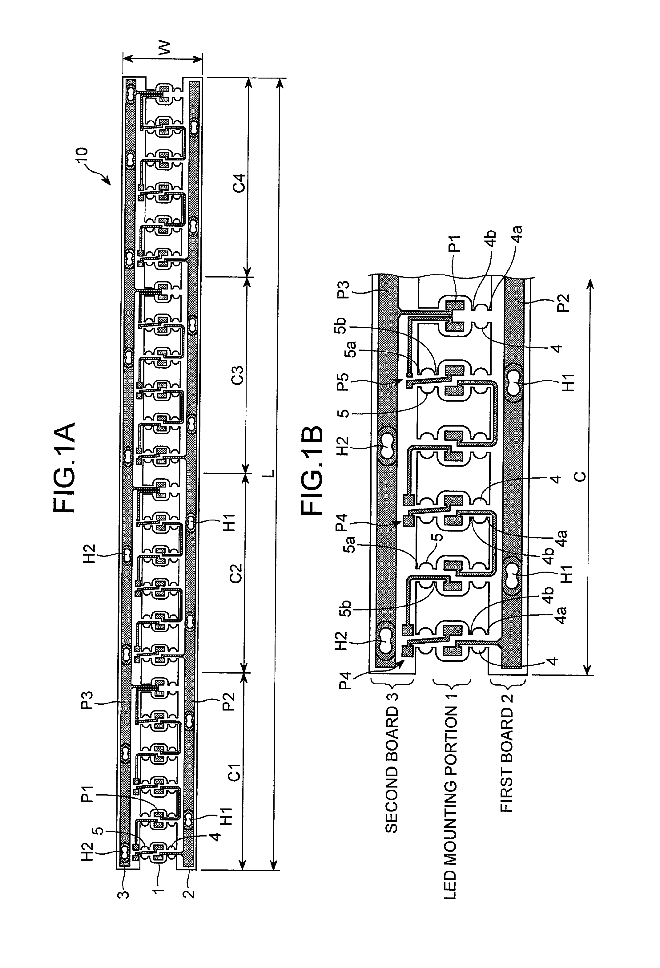
[0040]As shown in FIGS. 1A and 1B (FIG. 1A is a general plan view showing a single unit and FIG. 1B is an enlarged plan view showing a single circuit), an LED mounting circuit board (hereinafter referred to as a “circuit board”) 10 according to the present invention is provided with an LED mounting portion 1 in which a plurality of LEDs is mounted in an array on a central part in a transverse direction of a long belt-like flexible board, first and second boards 2 and 3 in which a feed pattern for causing a current to flow to an LED are provided on both sides in the transverse direction of the LED mounting portion 1, and the LED mounting portion 1 and the first and second boards 2 and 3 are formed to be bendable. In the present embodiment, the LED mounting portion 1 and the first board 2 are coupled through a coupling piece 4 having cut portions 4a and 4b provided on both ends, and the LED mounting portion 1 and the second board 3 are coupled through a coupling piece 5 having cut por...

second embodiment

[0059]Although the circuit board 10 in two units has a length L of 240 mm and a width W of 24 mm, the board has a thickness of 100 μm and a copper lamination (a conductive pattern) has a thickness of 35 μm to 50 μm in the second embodiment, the present invention is not restricted thereto.

[0060]Since the other structures and functions are the same as those in the first embodiment, description will be omitted.

[0061]The LED mounting circuit board 10 takes a bending configuration having a T-shape section as in the first embodiment, and furthermore, is also compatible with a configuration in which the first board 2 and the second board 3 are bent at a right angle with respect to the LED mounting portion 1 to take a U shape and a flexibility is thus damaged as shown in FIG. 14A and a configuration in which the cut portion 4b or 5b is bent at 180 degrees with respect to the LED mounting portion 1 toward the opposite surface of the first board 2 or the second board 3 to set an irradiating d...


PUM


Abstract

A belt-like flexible LED light can be bent in both an orthogonal direction to a light emitting direction and a vertical direction. Additionally, a circuit board and LED illuminating device are capable of implementing the LED light. An LED mounting circuit board, in which an LED mounting portion has a plurality of LEDs mounted in an array, is provided on a central part in a transverse direction of a long belt-like flexible board. Both sides of the LED mounting circuit board are in a transverse direction of the LED mounting portion and are provided with a first board and a second board having a feed pattern for causing a current to flow to the LEDs formed thereon. The LED mounting portion, the first board and second board are formed to be bendable and are used with the belt-like flexible LED light.

Description

FIELD OF THE INVENTION[0001]1. Background of the Invention[0002]The present invention relates to an LED (light emitting diode) mounting circuit board having a flexibility, a belt-like flexible LED light and an LED illuminating device using the same.[0003]2. Description of the Related Art[0004]When a plurality of SMD (Surface Mount Device surface mounting) type LEDs (Light Emitting Diodes) is linearly mounted on a circuit board and is turned ON, an LED light emitting direction is generally equivalent to a perpendicular direction to the circuit board. In this case, if the circuit board is manufactured by a belt-like FPC (Flexible Printed Circuit) which can easily be bent, it is possible to form a belt-like light emitting module which can be curved in the LED light emitting direction. A large number of products are fabricated as a tape light (for example, see Japanese Unexamined Patent Publication No. 2002-197901, Japanese Unexamined Patent Publication No. 2002-232009, Japanese Unexami...

Claims


Application Information

Patent Timeline
Patent Type & Authority Patents(United States)
IPC IPC(8): F21S4/00F21V21/00F21Y101/02F21Y103/00F21Y113/00
CPCF21S4/007F21Y2101/02Y10S362/80F21Y2113/005F21Y2103/003F21S4/26H05K1/028H05K1/189H05K3/0052H05K2201/055H05K2201/0969H05K2201/10106F21Y2103/10F21Y2115/10F21Y2113/13
Inventor ISHIBASHI, KAZUOHINAGO, SUETOSHI
Owner ATEX CO LTD
Learn More