Tiered sensing and resource allocation system for energy use optimization in commercial buildings

a resource allocation and energy use optimization technology, applied in the field of building control systems, can solve the problems of large data stores, inability to provide centralized information regarding the full state of the building, and inability to respond to changes in conditions fully centralized systems can be slow to provide centralized information, etc., to achieve high degree of performance, high cost of wired installation, and rapid updating

Inactive Publication Date: 2015-03-17
THE BOARD OF TRUSTEES OF THE LELAND STANFORD JUNIOR UNIV
View PDF7 Cites 4 Cited by
  • Summary
  • Abstract
  • Description
  • Claims
  • Application Information

AI Technical Summary

Benefits of technology

[0005]Embodiments of the present invention provide quality occupant performance while optimizing energy use for lighting in a commercial office building utilizing distributed sensing and control. A system according to preferred embodiments has zone-level controllers that gather set point preferences from building occupants, measure current actual light levels associated with the preferences, and regularly update light settings based on stored mappings of light fixtures to sensors to best meet the preferred light levels while minimizing energy use. A building-level server in the lighting control system defines energy use in terms of utility and uses utility curves reported by the zone controllers to determine resource allocation to the zones. The system combines distributed and centralized control to allow the building level to make appropriate energy allocations without being taxed with the burden of processing raw sensor data from the entire building. The decentralized, distributed zone controllers are able to respond quickly to changes and update lighting scenes as necessary while the centralized building level server is able to monitor system performance, set total energy use limits, initialize demand response, and manage the quality of the occupant experience. The system also allows a building manager to explicitly view the tradeoff between energy savings and performance for the occupants by incorporating occupant preferences into the allocation scheme.
[0008]Embodiments of the present invention provide a service-based approach that enables the explicit designation of acceptable service level standards and the inclusion of relative importance weighting for individuals and areas throughout the building.
[0009]This system enjoys advantages that arise from the tiered structure and use of utility curves at zone and building server. While most currently available technologies are either entirely centralized or entirely distributed, the tiered structure of this system allows for a centralized information repository and communication with the building manager as to the explicit performance tradeoff for energy use reduction while still providing rapid updating and response times locally. The utility curves allow for efficient trading to ensure a high degree of performance even in an energy constrained scenario. Implementing the prototype system wirelessly makes this system ideal for retrofit applications and for use in reconfigurable spaces due to the comparatively high cost of wired installation.

Problems solved by technology

Decentralized systems enable quick local response but are unable to provide centralized information regarding the full state of the building.
Fully centralized systems can be slow to respond to changes in conditions and require large stores of data.
Existing methods typically do not allow for flexibility in addressing variable conditions across a space nor do they allow for the incorporation of variable preferences.
These systems are also incapable of truly optimizing restricted energy resources across a building and cannot inform decision makers of the performance costs of energy use reduction.
Moreover, such systems are not able to provide rapid updating and response times, especially in large buildings.

Method used


Image

  • Tiered sensing and resource allocation system for energy use optimization in commercial buildings
  • Tiered sensing and resource allocation system for energy use optimization in commercial buildings
  • Tiered sensing and resource allocation system for energy use optimization in commercial buildings

Examples


Embodiment Construction

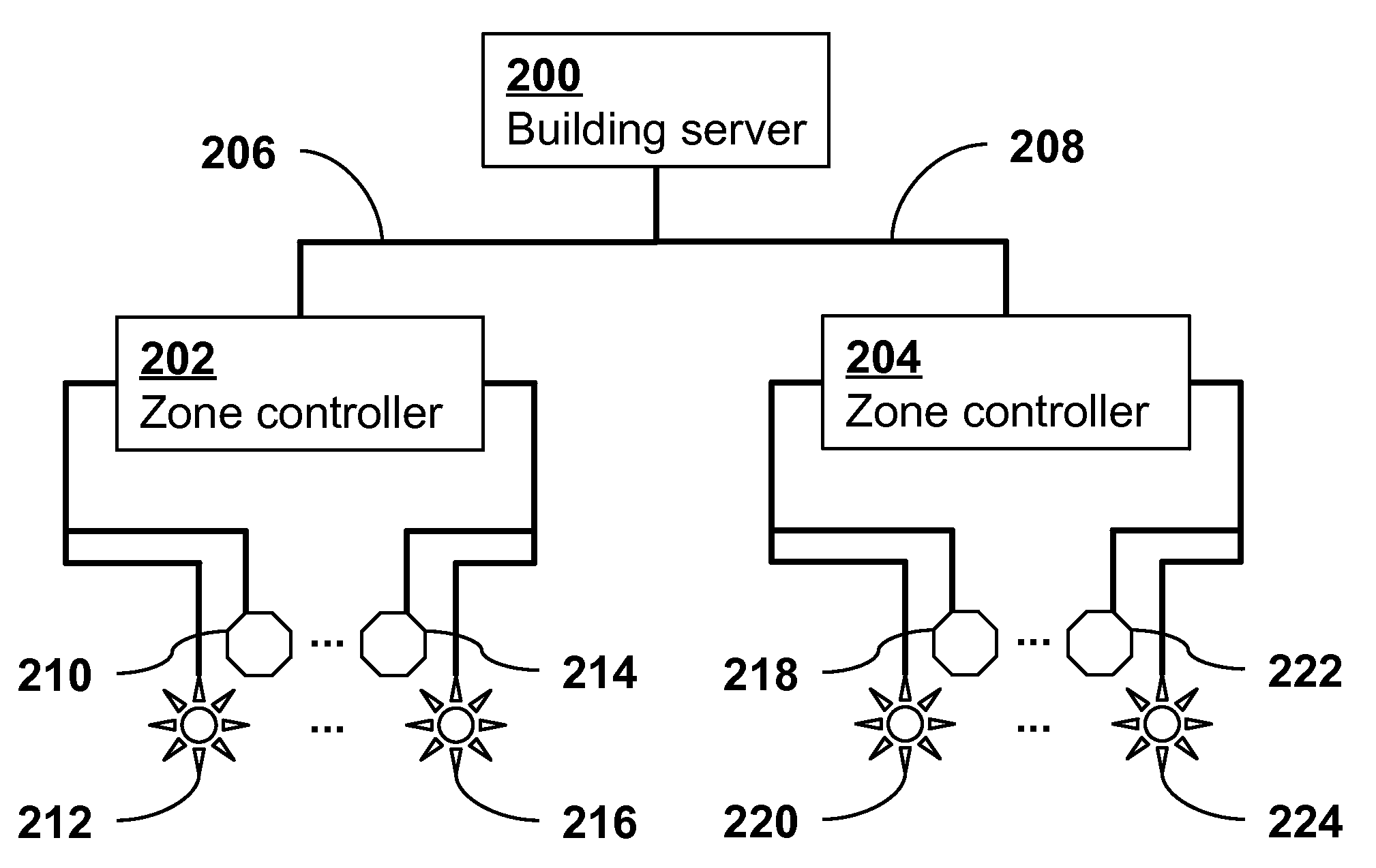
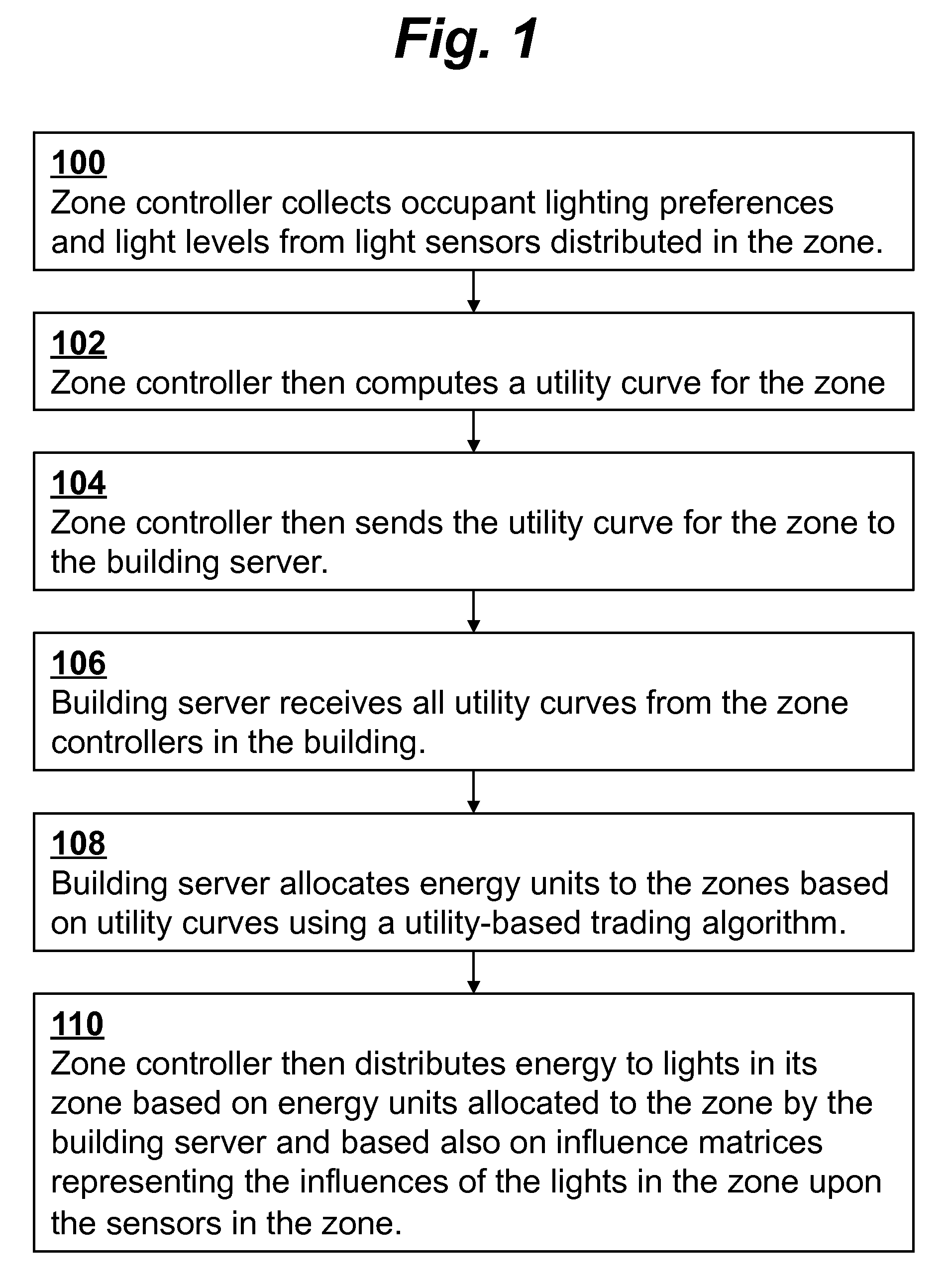
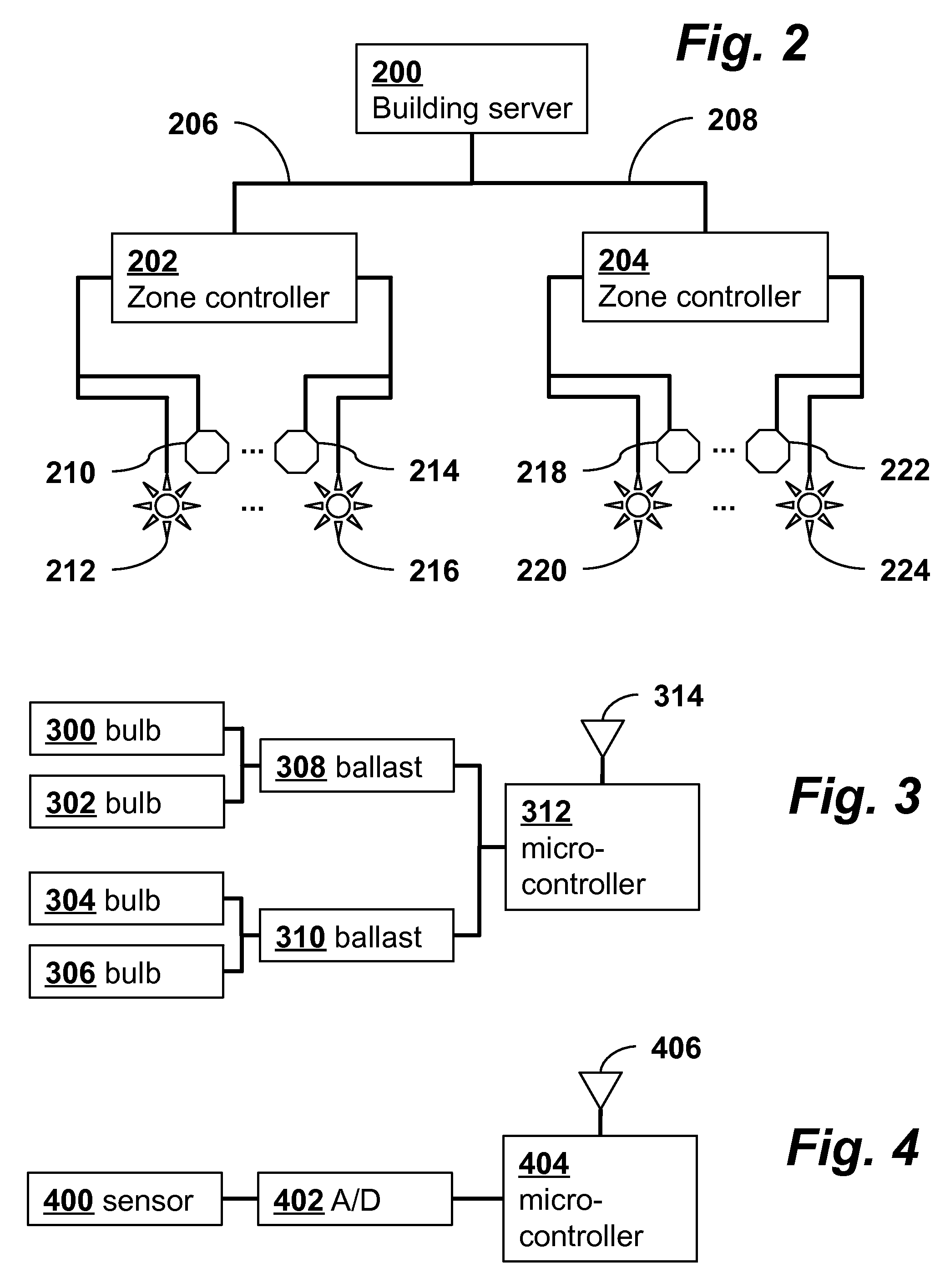
[0020]FIG. 1 is a flow diagram showing an outline of a method for building lighting control according to an embodiment of the invention. The method may be implemented by a system as shown in the schematic block diagram of FIG. 2. According to this embodiment, the lighting control system is comprised of three levels. At the base level are distributed sensing units 210, 214, 218, 222 tasked with obtaining the current light level, allowing the occupant to request a preferred light level, and sensing occupancy (i.e., determining whether an occupant is present). Also included in the base level of the system are control units 212, 216, 220, 224 capable of dimming the lighting in the space. At the middle level are zone managers 202, 204 each of which coordinates the sensing units and control units in its zone. A zone may be defined as a large shared office space or several smaller offices within a building. Ideally the zones are photo-isolated from one another, although small levels of cro...


PUM


Abstract

A building lighting control system includes a central building server, distributed zone controllers, and light sensors and control units in each zone. Using occupant lighting preferences, occupancy state, and light levels, each zone controller computes a utility curve which represents the relationship between energy use and service level in the zone. The building server zone receives utility curves from all the zones and allocates energy units to the zones based on the utility curves using a utility-based trading algorithm in order to optimize service levels with minimal energy. Each zone controller then distributes energy to lights in its zone based on energy units allocated to the zone by the building server and based also on influence matrices representing the influences of the lights in the zone upon the sensors in the zone. The building server may also compute and output long-term operational information of the building.

Description

CROSS-REFERENCE TO RELATED APPLICATIONS[0001]This application claims priority from U.S. Provisional Patent Application 61 / 522,515 filed Aug. 11, 2011, which is incorporated herein by reference.FIELD OF THE INVENTION[0002]The present invention relates generally to methods and systems for building control systems. More specifically, it relates to tiered lighting control systems for buildings.BACKGROUND OF THE INVENTION[0003]Building lighting control management systems are designed to help automate the adjustment of lighting levels inside buildings to appropriate levels, often while also attempting to reduce unnecessary lighting and energy use. Typically, such systems use either a completely decentralized or completely centralized approach.[0004]Decentralized systems enable quick local response but are unable to provide centralized information regarding the full state of the building. Fully centralized systems can be slow to respond to changes in conditions and require large stores of ...

Claims


Application Information

Patent Timeline
Patent Type & Authority Patents(United States)
IPC IPC(8): H05B37/02
CPCH05B37/0245H05B47/175
Inventor ASKIN, AMANDA C.LAW, KINCHO H.
Owner THE BOARD OF TRUSTEES OF THE LELAND STANFORD JUNIOR UNIV
Why Eureka
Try Eureka