
Wide-angle optical system, and imaging apparatus incorporating the same

a wide-angle optical system and imaging apparatus technology, applied in the field of wide-angle optical systems and imaging apparatuses incorporating the same, can solve the problems of difficult design of optical systems that are reduced, and achieve the effects of reducing the negative influence of ill-balanced aberrations, minimizing or eliminating negative influences of ill-balanced aberrations, and good correction

Inactive Publication Date: 2015-03-17
OM DIGITAL SOLUTIONS CORP
View PDF16 Cites 0 Cited by
  • Summary
  • Abstract
  • Description
  • Claims
  • Application Information

AI Technical Summary

Benefits of technology

This configuration allows for effective correction of various aberrations, including field curvature and astigmatism, while maintaining a telecentric feature and ensuring high optical performance across different focusing positions with a low lenses count.

Problems solved by technology

With fewer lenses, however, it is difficult to design an optical system that is reduced in terms of aberrations while making sure any desired wide angle, and reduced in terms of field curvature fluctuations upon focusing while keeping the telecentric feature intact.

Method used


Image

  • Wide-angle optical system, and imaging apparatus incorporating the same
  • Wide-angle optical system, and imaging apparatus incorporating the same
  • Wide-angle optical system, and imaging apparatus incorporating the same

Examples


example 1

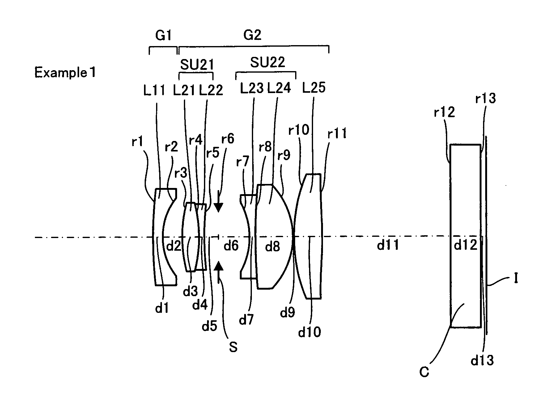
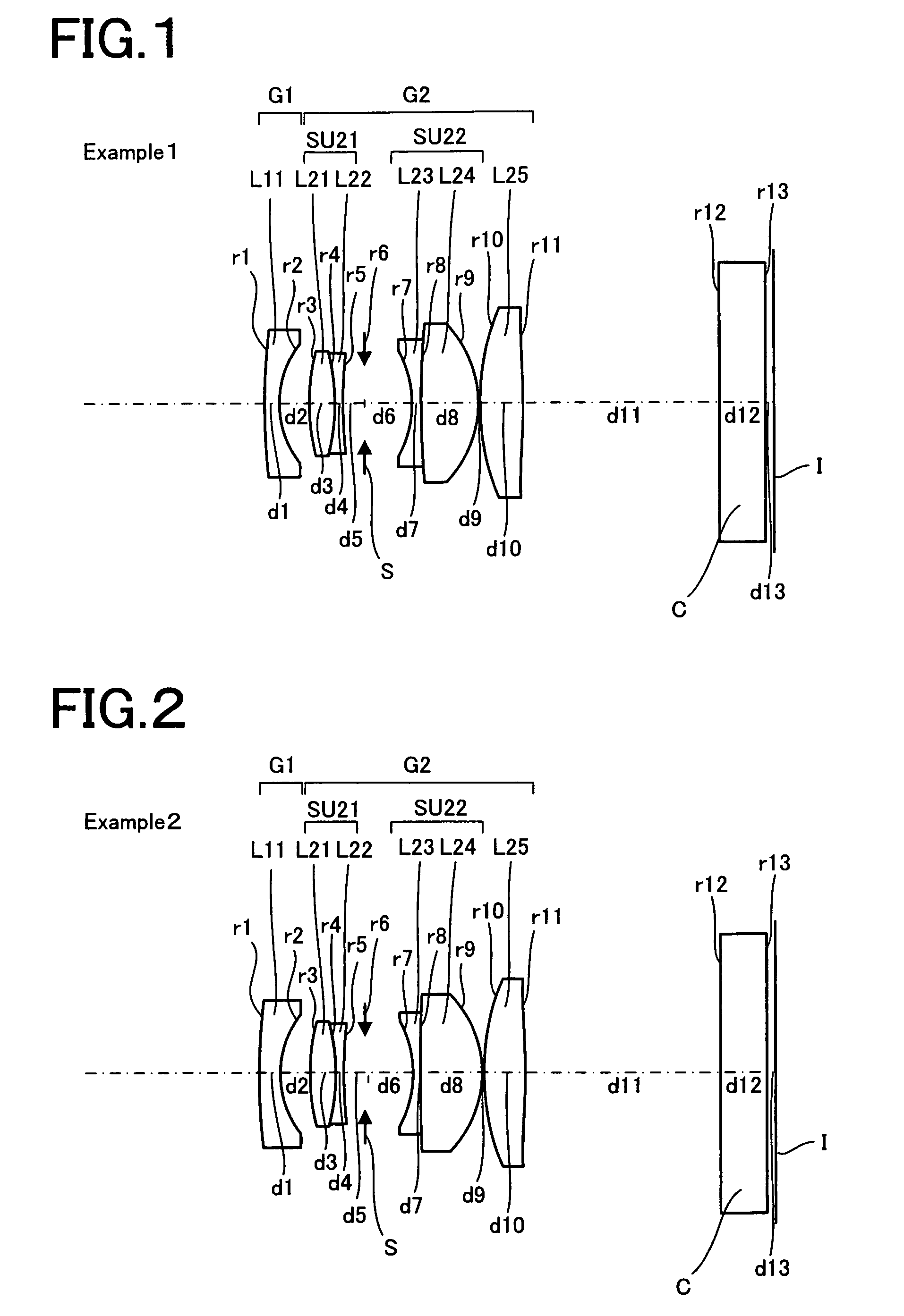
Numeral Example 1

[0128]

Unit mmSurface DataSurface Numberrdndνd 157.7561.351.4874970.23 28.7482.61 318.4052.281.8340037.16 4−18.6830.691.5673242.82 547.9291.84 6 (Stop)∞4.17 7−9.7990.801.7521125.05 891.6815.011.7291654.68 9−10.3160.1310 (Aspheric Surface)22.8033.801.5307155.6711 (Aspheric Surface)−63.92817.1512∞4.051.5163364.1413∞0.75Image Plane∞Aspheric Data10th SurfaceK = −0.016, A4 = −4.37943E−08, A6 = 3.51554E−08,A8 = 2.38957E−0911th SurfaceK = −27.269, A4 = 4.45183E−05, A6 = −2.16109E−08,A8 = 3.47481E−09Data Setf17.23Fno2.89Angle of View (2 ω)71.67°Image Height11.15B F (in air)20.56Full Lens Length43.25

example 2

Numeral Example 2

[0129]

Unit mmSurface DataSurface Numberrdndνd 154.3911.941.4874970.23 28.4312.63 319.4172.281.8340037.16 4−17.5480.691.5673242.82 548.3631.84 6 (Stop)∞4.17 7−10.4390.741.7521125.05 8217.9085.421.7291654.68 9−10.5920.0910 (Aspheric Surface)21.8093.871.4970081.5411 (Aspheric Surface)−58.42817.1512∞4.051.5163364.1413∞0.75Image Plane∞Aspheric Data10th SurfaceK = −0.006, A4 = 6.36012E−08, A6 = 5.09958E−10,A8 = 3.71078E−0911th SurfaceK = −26.933, A4 = 4.41271E−05, A6 = −1.00023E−07,A8 = 5.51439E−09Data Setf16.81Fno2.89Angle of View (2 ω)73.48°Image Height11.15B F (in air)20.55Full Lens Length44.23

example 3

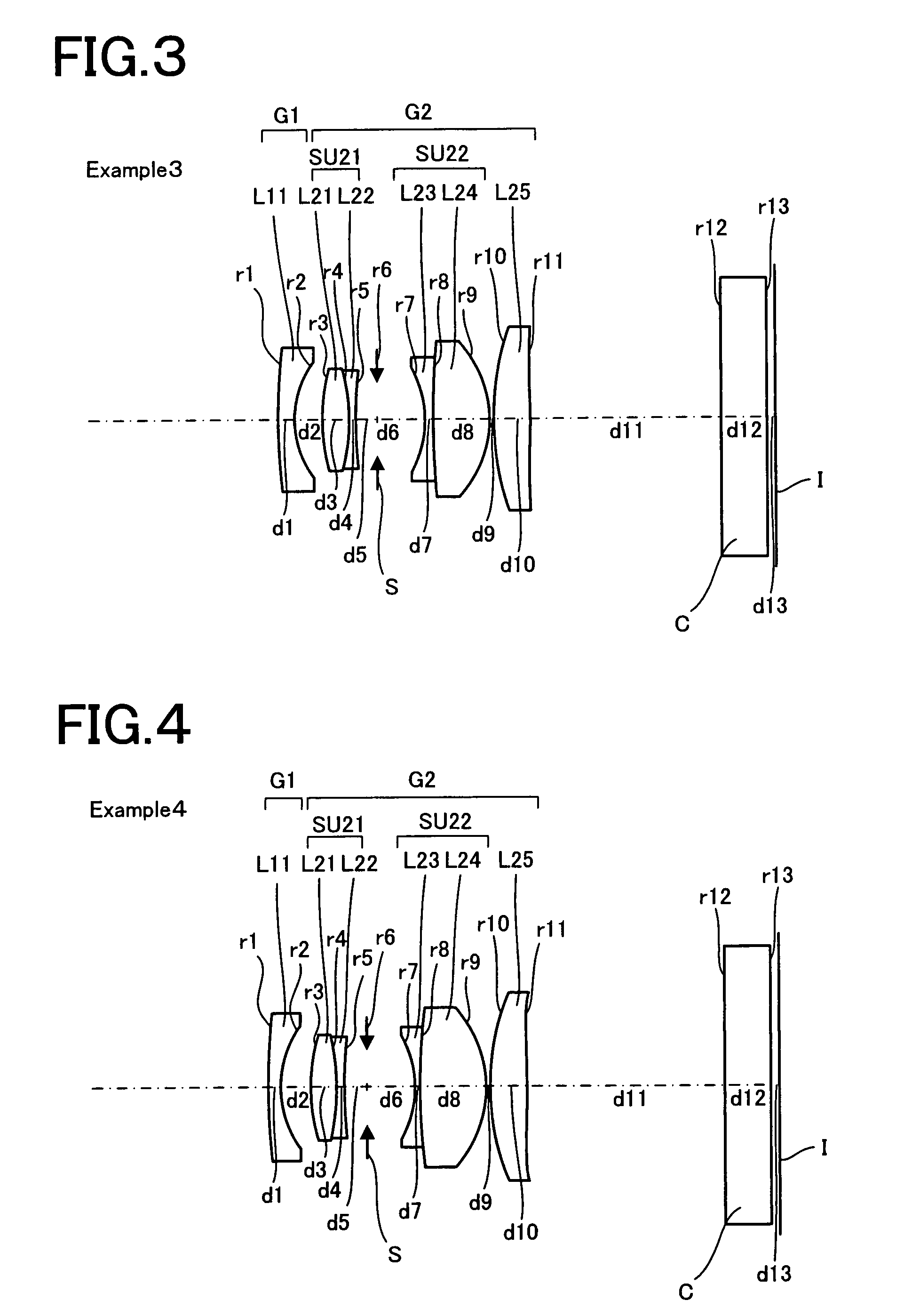
Numeral Example 3

[0130]

Unit mmSurface DataSurface Numberrdndνd 151.3991.631.4874970.23 29.0392.48 318.2642.281.8340037.16 4−20.6870.691.5673242.82 550.0271.84 6 (Stop)∞4.17 7−10.2430.831.7521125.05 886.7855.031.7291654.68 9−10.6860.3110 (Aspheric Surface)28.4613.351.6935053.2111 (Aspheric Surface)−104.28117.1512∞4.051.5163364.1413∞0.75Image Plane∞Aspheric Data10th SurfaceK = 1.326, A4 = 1.72221E−05, A6 = 5.40432E−11, A8 = 2.82500E−0911th SurfaceK = −124.089, A4 = 4.96066E−05, A6 = 8.69061E−10, A8 = 4.18831−09Data Setf17.70Fno2.89Angle of View (2 ω)69.42°Image Height11.15B F (in air)20.55Full Lens Length43.18


PUM


Abstract

The wide-angle optical system of the invention comprises, in order from its object side, a first lens group having negative refracting power and a second lens group having positive refracting power. The second lens group comprises, in order from the object side, a first cemented doublet lens, an aperture stop, a second cemented doublet lens and a first double-convex lens. The widest separation among axial air separations except a back focus provides an axial space for receiving the aperture stop. The optical system is divided into the first lens group and the second lens group with the second widest air separation as a boundary. Focusing is implemented by letting the whole optical system out. The optical system satisfies Condition (1).1.4≦nd≦1.8  (1)Here nd is the d-line refractive index of the first double-convex lens.

Description

BACKGROUND OF THE INVENTION[0001]For a wide-angle lens for digital cameras, there is increasing demand toward an optical system having a long back focus, because of the need for providing a space for receiving optical elements such as filters just in front of an electronic imaging plane while making sure a wide angle of view. As such an optical system, there has been a retrofocus type optical system widely adopted, which comprises a front unit of negative refracting power and a rear unit of positive refracting power. Upon incidence on the electronic imaging plane of a light beam passing through the optical system, the quantity of rim light decreases, giving rise to shadings or color shifts, at a time when the incident light beams enter obliquely with respect to the optical axis (the so-called oblique incidence). To solve these problems, there has been an optical system proposed, which keeps hold of the telecentric feature of the incident light beam. Such optical systems have been pr...

Claims


Application Information

Patent Timeline
Patent Type & Authority Patents(United States)
IPC IPC(8): G02B13/04G02B9/34
CPCG02B13/04
Inventor UEMURA, RYOSUKE
Owner OM DIGITAL SOLUTIONS CORP
Learn More