

Method of and apparatus for positioning a tool
a tool and positioning technology, applied in the field of methods and apparatus for positioning tools, can solve the problems of inability to release, high clamping pressure, and inability to move the drive, so as to save significant time, improve cost effectiveness and safety of installation, and simple and fast manner
- Summary
- Abstract
- Description
- Claims
- Application Information
AI Technical Summary
Benefits of technology
Problems solved by technology
Method used
Image

Examples
Embodiment Construction
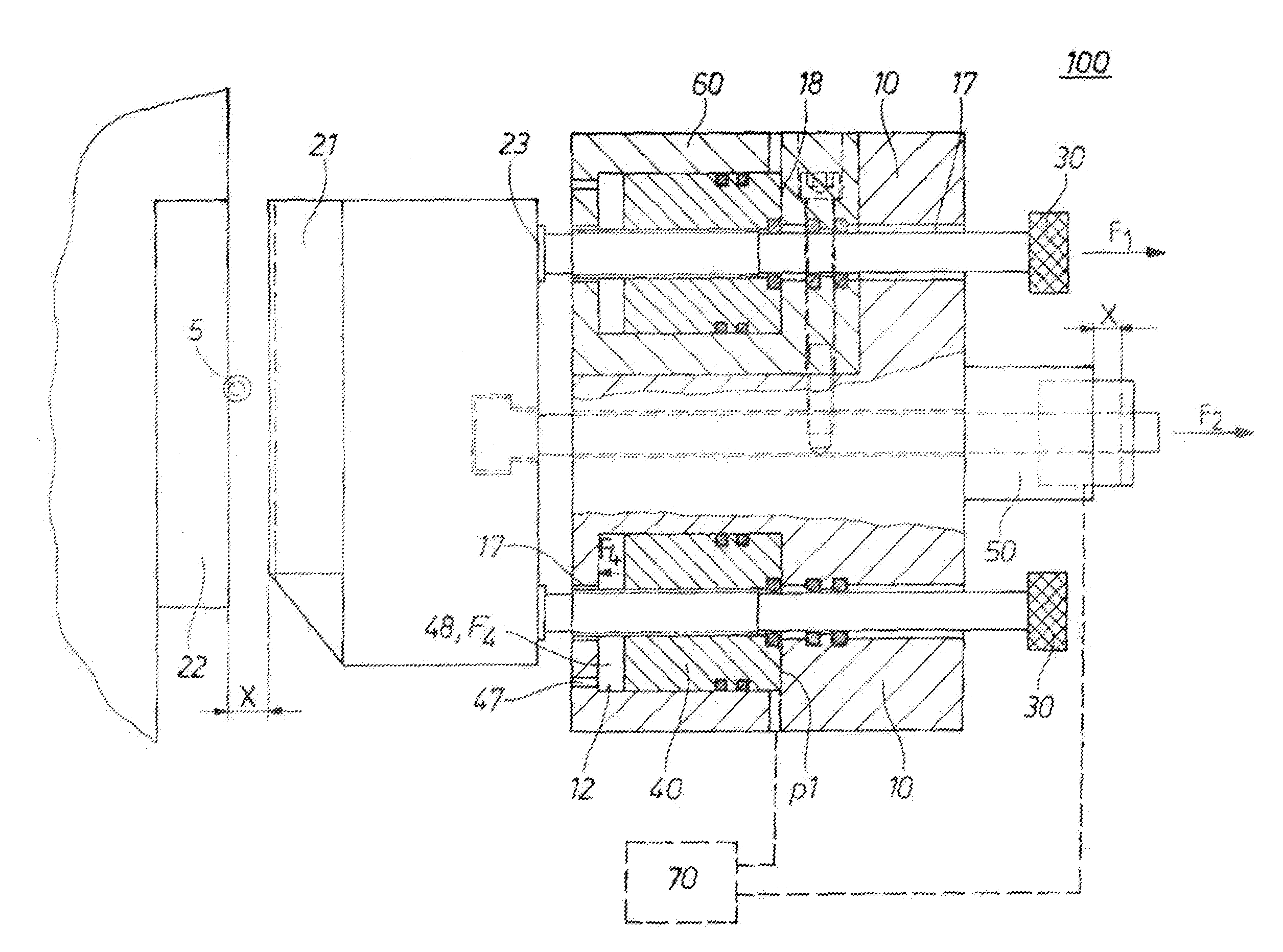
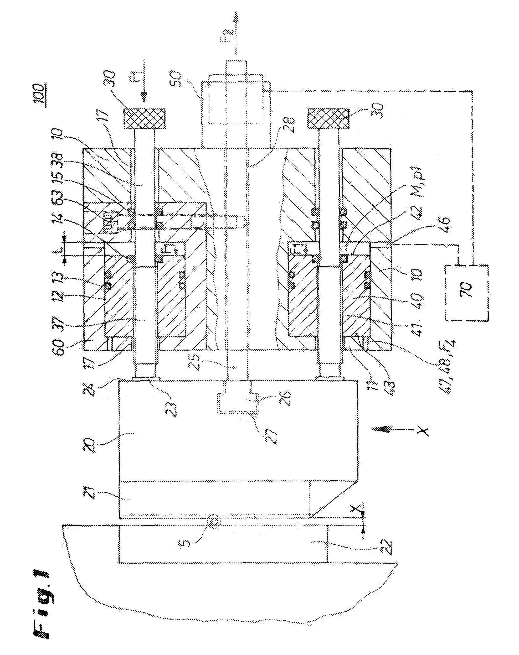
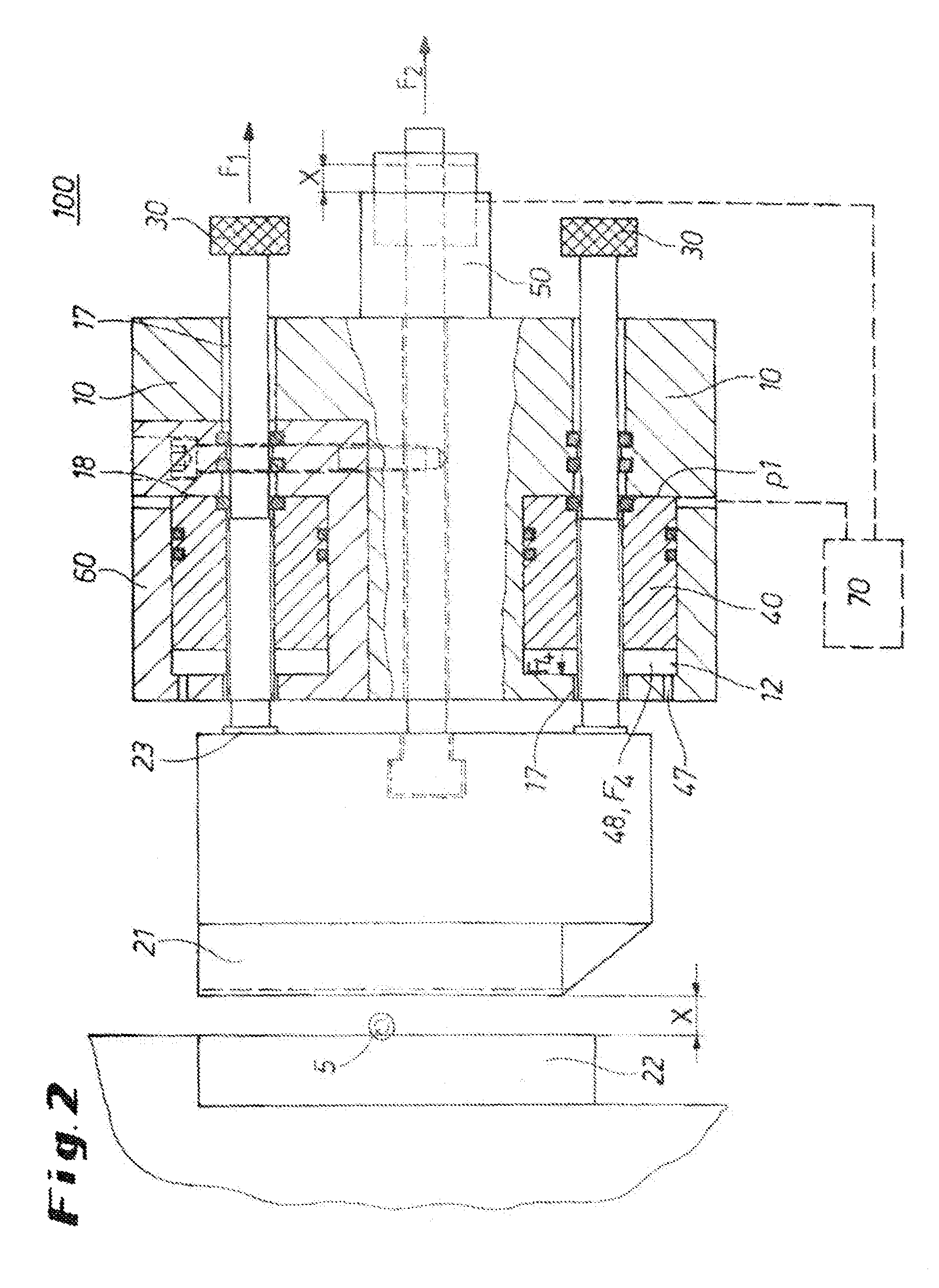
[0003]It is the object of the invention to provide a method of and apparatus for positioning a tool in a profile rolling machine that allow a fast and easy opening as well as a fast repositioning of the rolling tool into its starting position. Moreover, cost effectiveness and safety of the installation is to be improved.
[0004]This object is solved by an apparatus for positioning a tool in a profile rolling machine comprising a base configured to have at least one first bore, and at least one adjusting spindle having a tool stop, which adjusting spindle is mounted in a position-variable manner in the first bore of the base. A retraction rod is adjustable as to position for positioning the first tool with a tractive force against the tool stop. The first bore is locally expanded to form a cylinder chamber. A piston can move axially in this cylinder chamber. The piston and the cylinder chamber together form a piston-cylinder unit. A pressure connection is provided in the base for intro...
PUM
| Property | Measurement | Unit |
|---|---|---|
| tractive force | aaaaa | aaaaa |
| pressure | aaaaa | aaaaa |
| clamping pressure | aaaaa | aaaaa |
Abstract
Description
Claims
Application Information