

Method of and apparatus for positioning a tool
- Summary
- Abstract
- Description
- Claims
- Application Information
AI Technical Summary
Benefits of technology
Problems solved by technology
Method used
Image

Examples
Embodiment Construction
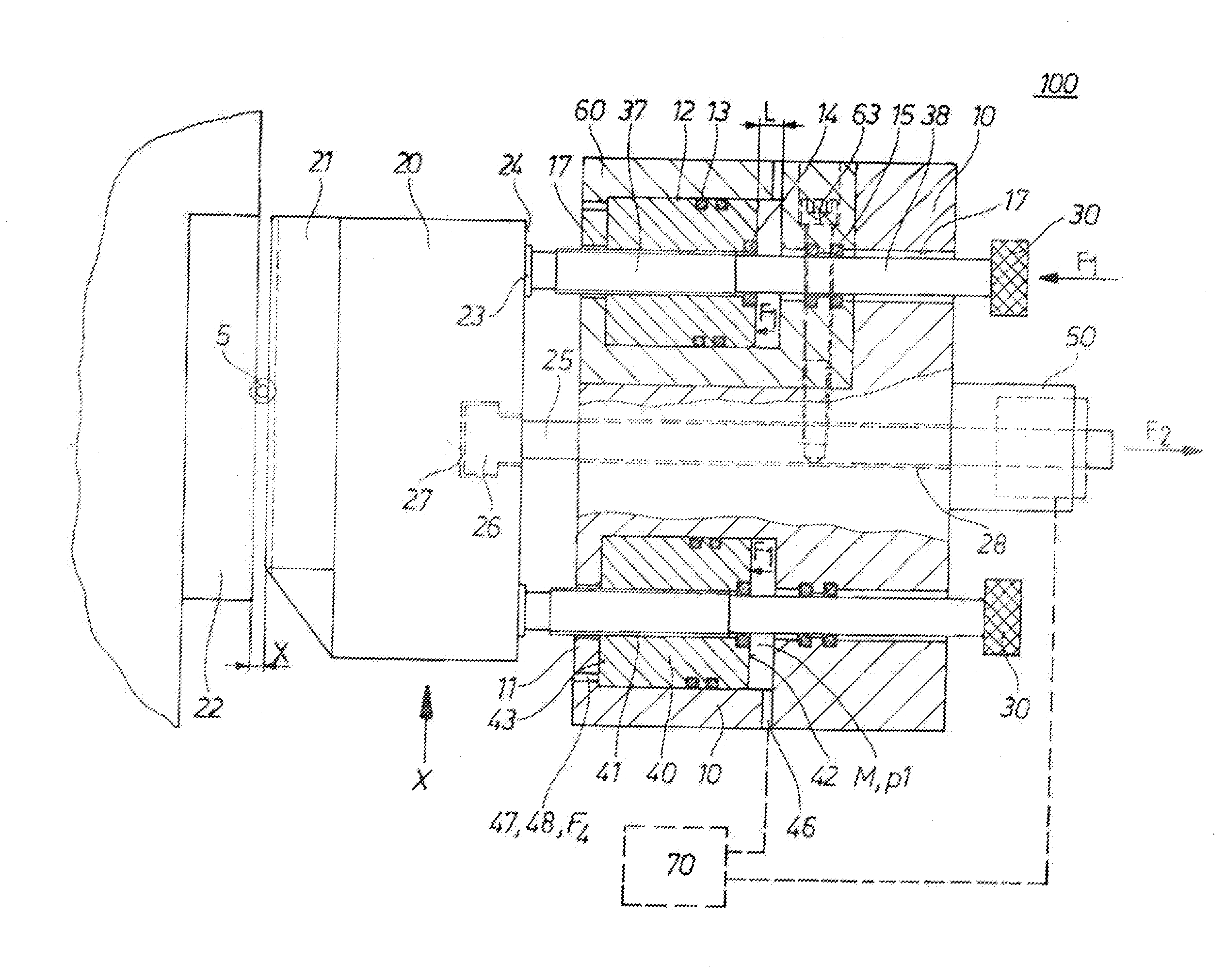
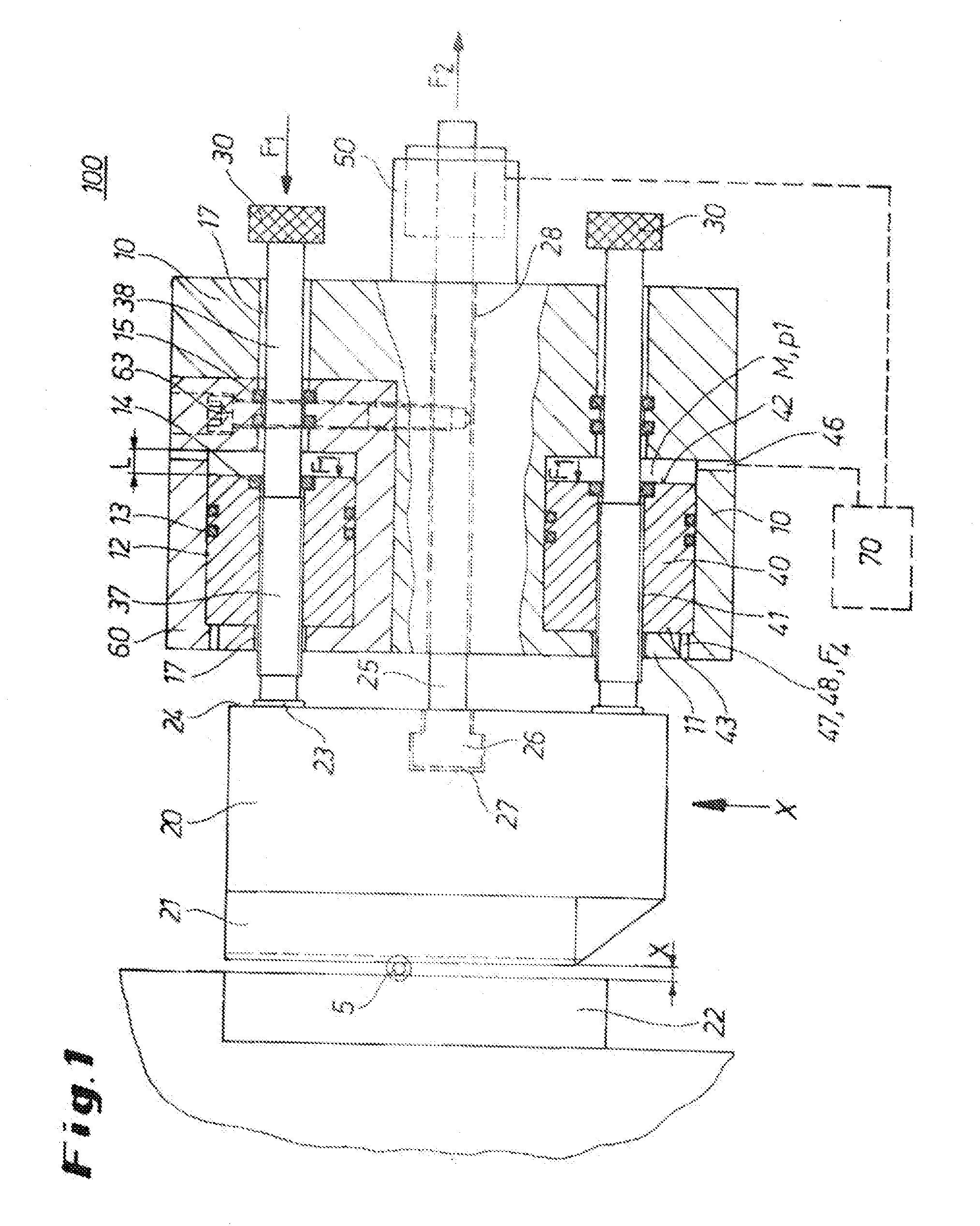
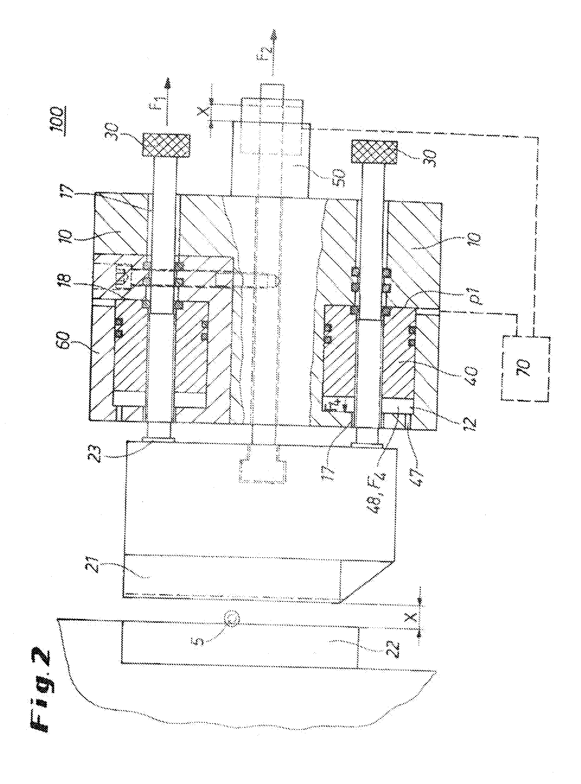
[0003]It is the object of the invention to provide a method of and apparatus for positioning a tool in a profile rolling machine that allow a fast and easy opening as well as a fast repositioning of the rolling tool into its starting position. Moreover, cost effectiveness and safety of the installation is to be improved.
[0004]This object is solved by an apparatus for positioning a tool in a profile rolling machine comprising a base configured to have at least one first bore, and at least one adjusting spindle having a tool stop, which adjusting spindle is mounted in a position-variable manner in the first bore of the base. A retraction rod is adjustable as to position for positioning the first tool with a tractive force against the tool stop. The first bore is locally expanded to form a cylinder chamber. A piston can move axially in this cylinder chamber. The piston and the cylinder chamber together form a piston-cylinder unit. A pressure connection is provided in the base for intro...
PUM
| Property | Measurement | Unit |
|---|---|---|
| Force | aaaaa | aaaaa |
| Pressure | aaaaa | aaaaa |
| Displacement | aaaaa | aaaaa |
Abstract
Description
Claims
Application Information