Turbine vane airfoil reconfiguration system

a technology of airfoil and turbine vane, which is applied in the field of turbine vane, can solve the problems of affecting the performance of the turbine engine, severely affecting the lifecycle of the airfoil and inner and outer shroud, and conventional systems are time-consuming, so as to facilitate the twisting of the turbine vane segment, significant time and cost savings, and remove any distortion effects of welding

Inactive Publication Date: 2007-04-19
CHROMALLOY GAS TURBINE
View PDF32 Cites 16 Cited by
  • Summary
  • Abstract
  • Description
  • Claims
  • Application Information

AI Technical Summary

Benefits of technology

[0007] The system may be used to straighten an airfoil of a turbine vane segment. A turbine vane segment may be attached to the system by engaging an outer shroud of the turbine vane segment with reaction arms supported by the fixture. The reaction arms may be inserted into recesses within an outer surface of the shroud. An inner shroud of the turbine vane segment may be engaged by a force exertion system for exerting a force in a direction that is generally tangential to the outer shroud. Orifices may be created in a convex side, also referred to as the suction side, of an airfoil portion of the turbine vane segment proximate to the outer shroud. The orifices may extend generally parallel to a filleted edge between the outer shroud and the at least one airfoil. The airfoil may be heated to facilitate twisting of the turbine vane segment. Once heated, a force may be applied to the inner shroud in a direction that is generally tangential to the outer shroud until the airfoil has been twisted to a desired position. After twisting, the orifices in the airfoil may be sealed. In at least one embodiment, the orifices may be sealed while the airfoil remains heated. The orifices may be sealed with a weld or other appropriate method. The airfoil may be reheated after welding to remove any distortion effects from welding.
[0008] An advantage of this invention is that the outer housing may be secured and a force may be applied to the inner shroud of the housing without additional bracing to twist the turbine vane airfoil to a desired position. This system and method results in a very efficient system capable of removing lean, twist, or racking, or any combination thereof, in a single system.
[0009] Another advantage of this invention is that the system is capable of repairing turbine vane segments effectively such that the repaired turbine vane segments are comparable to newly manufactured, unused turbine vane segments and are capable of replacing the newly manufactured, unused turbine vane segments, which is a feat not easily accomplished using conventional technologies. Thus, this invention results in significant time and cost savings.

Problems solved by technology

Such distortion conditions negatively affect performance of the turbine engine and may severely affect the lifecycle of the airfoil and inner and outer shrouds.
However, conventional systems are time consuming.
For instance, twist may be removed from an airfoil using a furnace cycle; yet, a furnace cycle is very time consuming.
In addition, restoring a damaged airfoil to satisfactory tolerances is very difficult using conventional systems.

Method used


Image

  • Turbine vane airfoil reconfiguration system
  • Turbine vane airfoil reconfiguration system
  • Turbine vane airfoil reconfiguration system

Examples


Embodiment Construction

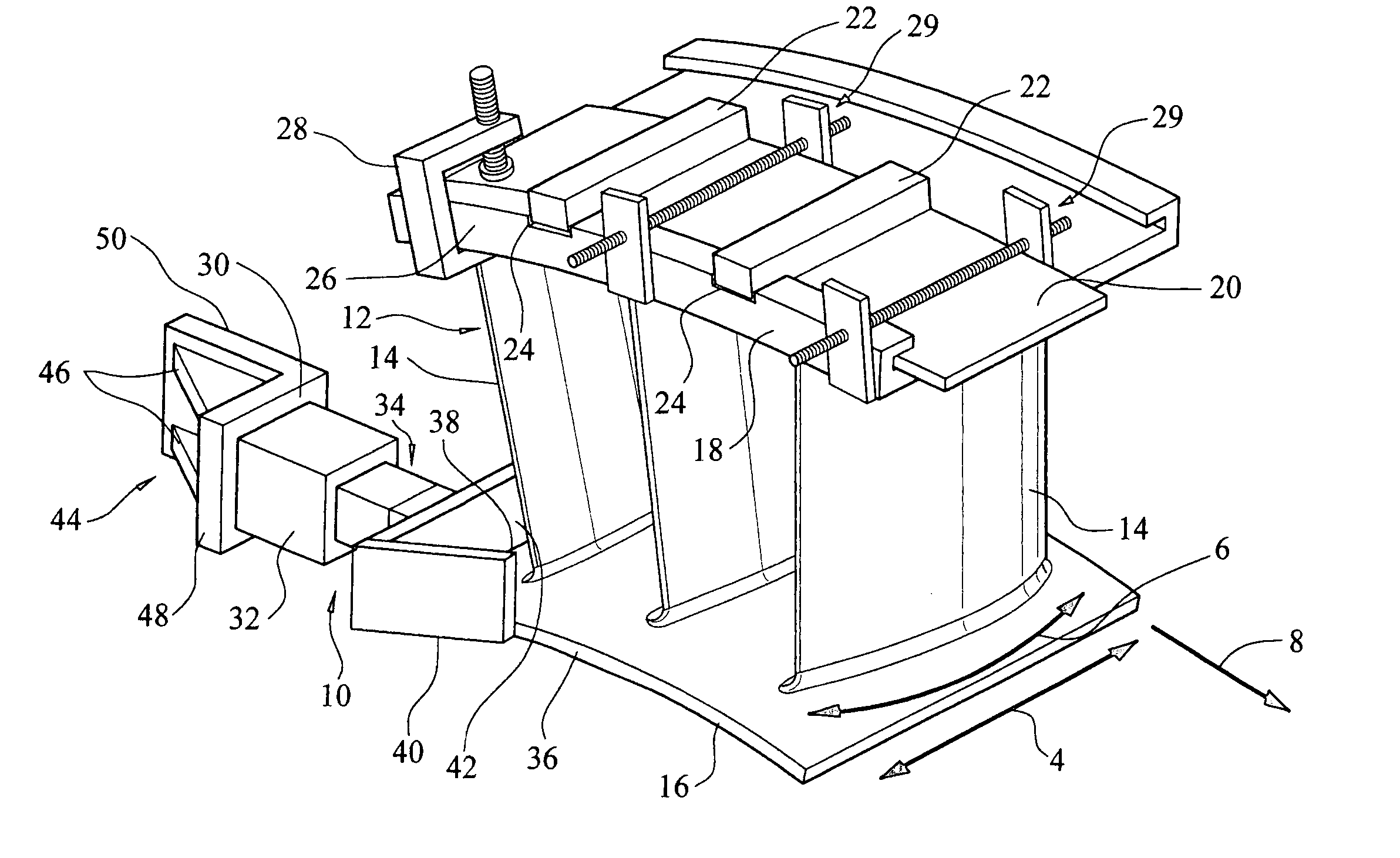
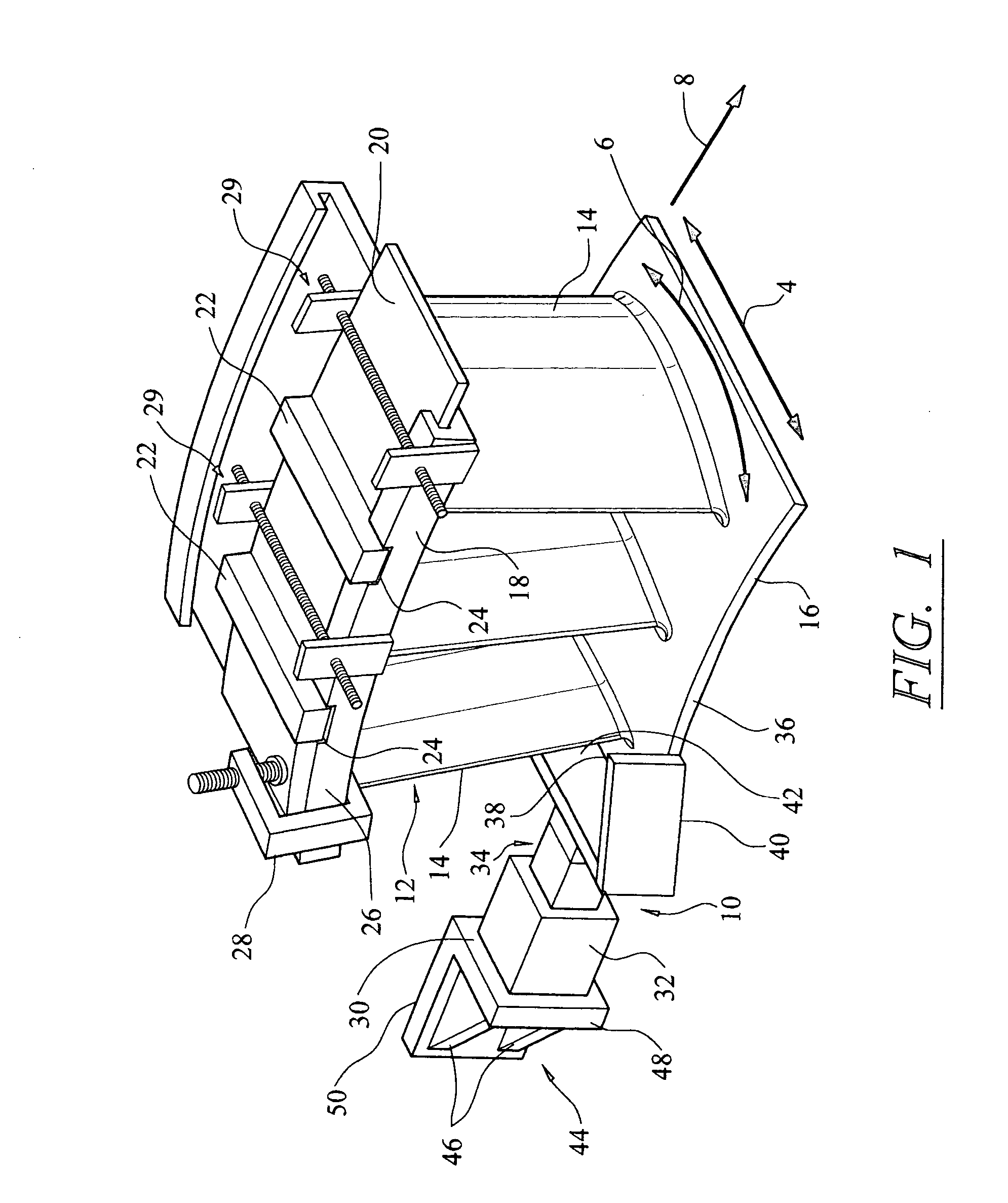
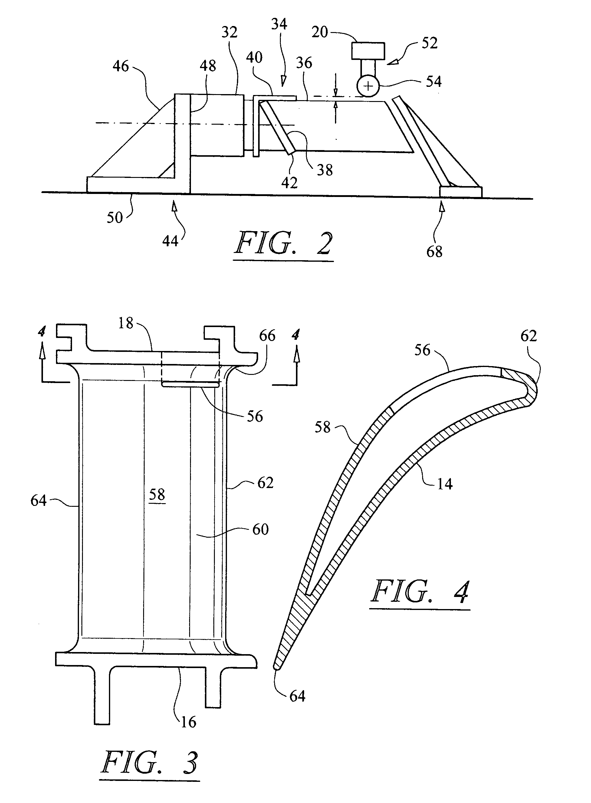
[0016] As shown in FIGS. 1-4, this invention is directed to system 10 for reconfiguring a turbine vane segment 12. In at least one embodiment, the system 10 may be used to straighten an airfoil 14 of a turbine vane segment 12 to remove lean 4, twist 6, or racking 8, or any combination thereof. The airfoil 14 may be straightened by applying a force to an inner shroud 16 of the turbine vane segment 12 that is generally tangential to an outer shroud 18 of the turbine vane segment 12.

[0017] As shown in FIG. 1, the system 10 may be formed from a fixture 20 configured to support one or more reaction arms 22. The reaction arms 22 may be configured to fit in recesses 24 on an outer surface 26 of an outer shroud 18 of the turbine vane segment 12 to position the turbine vane segment 12 within the system 10 and to prevent the outer shroud 18 from moving. The fixture 20 may be any device capable of supporting the turbine vane segment 12, and specifically, the outer shroud 18 of the segment 12....


PUM

PropertyMeasurementUnit
temperatureaaaaaaaaaa
lengthaaaaaaaaaa

Abstract

A system and method for reconfiguring an airfoil of a turbine vane segment. In at least one embodiment, the system may be used to straighten an airfoil of a turbine vane segment to remove lean, twist, or racking, or any combination thereof. The airfoil may be straightened by applying a load to an inner shroud in a direction that is generally tangential to an outer shroud of the turbine vane segment. Orifices may be cut into the airfoil suction side, inboard of the outer shroud, to facilitate the straightening process. The orifices may be sealed upon completion of the process.

Description

FIELD OF THE INVENTION [0001] This invention is directed generally to turbine vanes, and more particularly to turbine vane distortion correction systems. BACKGROUND [0002] Airfoils of turbine vane segments often distort during use in a turbine engine in one or more of four ways. For instance, airfoils may lean, which is downstream deflection. Airfoils may twist, which is rotation of the inner shroud about a longitudinal axis extending between the inner and outer shrouds. Airfoils may be subjected to racking, which is inner shroud circumferential rotation about an engine centerline relative to the outer housing. Airfoils may also droop, which occurs when down stream portions of the outer housing deflect into the gas path. Such distortion conditions negatively affect performance of the turbine engine and may severely affect the lifecycle of the airfoil and inner and outer shrouds. [0003] Conventional systems exist for removing twist from airfoils. However, conventional systems are tim...

Claims


Application Information

Patent Timeline
Patent Type & Authority Applications(United States)
IPC IPC(8): B21K21/16B23P6/00
CPCB23P6/002F01D5/005F05D2230/80Y10T29/49718Y10T29/49716Y10T29/49325Y10T29/49316Y10T29/53Y10T29/49336Y10T29/37Y10T29/49318
Inventor GOSLING, MARTIN C.DAVIS, JEFFERSONKANG, YONG
Owner CHROMALLOY GAS TURBINE
Why Eureka
Try Eureka