Projection exposure methods and apparatus, and projection optical systems

a technology of projection optical system and projection exposure method, which is applied in the direction of photomechanical apparatus, instruments, printers, etc., can solve the problems of limited material availability, limit the practical band narrowing, and limit the application of material

Inactive Publication Date: 2003-08-07
NIKON CORP
View PDF0 Cites 37 Cited by
  • Summary
  • Abstract
  • Description
  • Claims
  • Application Information

AI Technical Summary

Benefits of technology

0041] A first microdevice fabrication method according to the present invention is a method of fabricating a microdevice having a predetermined circuit pattern, comprising: a step of projecting an image of the pattern onto the workpiece to effect exposure thereof, using the foregoing exposure method; and a step of developing the workpiece after the projection exposure.
0042] Next, for accomplishing the foregoing first or second object, a fifth projection exposure apparatus according to the present invention is a projection exposure apparatus for projecting a pattern on a projection master onto a workpiece to effect exposure thereof, comprising: an illumination optical system for supplying exposure light of a wavelength of not more than 200 nm to the projection mast

Problems solved by technology

Although the aforementioned excimer lasers, halogen molecular lasers, etc. are available as light sources in the vacuum ultraviolet region of wavelengths not more than 200 nm, there are limits to practical band narrowing thereof.
Since lim

Method used


Image

  • Projection exposure methods and apparatus, and projection optical systems
  • Projection exposure methods and apparatus, and projection optical systems
  • Projection exposure methods and apparatus, and projection optical systems

Examples


first embodiment

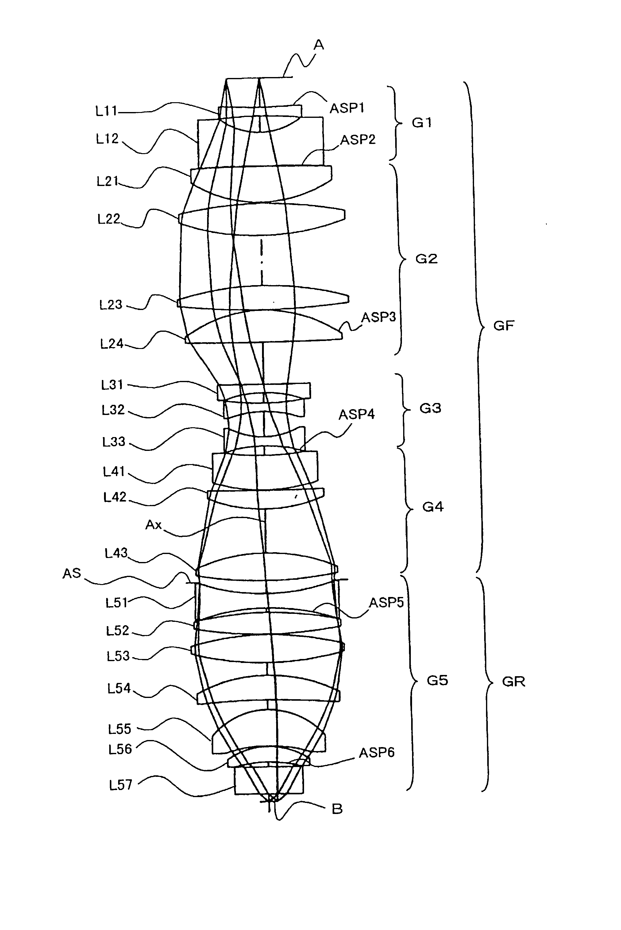
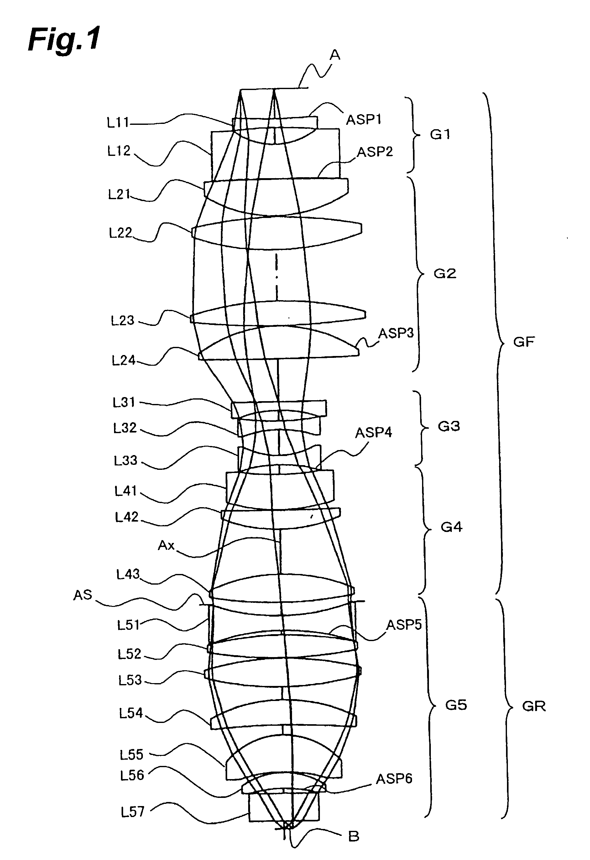
[0121] FIG. 1 is the optical path diagram of the projection optical system PL according to the

[0122] The projection optical system PL of the first embodiment uses the wavelength of 157.62 nm supplied from the band-narrowed F.sub.2 laser, as a reference wavelength and the chromatic aberration is corrected in the range of the wavelength band .+-.0.2 pm for the reference wavelength. In the first embodiment, all the radiation-transmitting refractors (lenses L11 to L57) in the projection optical system PL are made of fluorite (calcium fluoride, CaF.sub.2).

[0123] As shown in FIG. 1, the projection optical system PL of the first embodiment has the front lens unit GF of the positive refracting power, the aperture stop AS, and the rear lens unit GR of the positive refracting power in the order named from the first surface A side. According to another grouping, the projection optical system PL of the first embodiment has the negative, first lens unit G1, the positive, second lens unit G2, the...

second embodiment

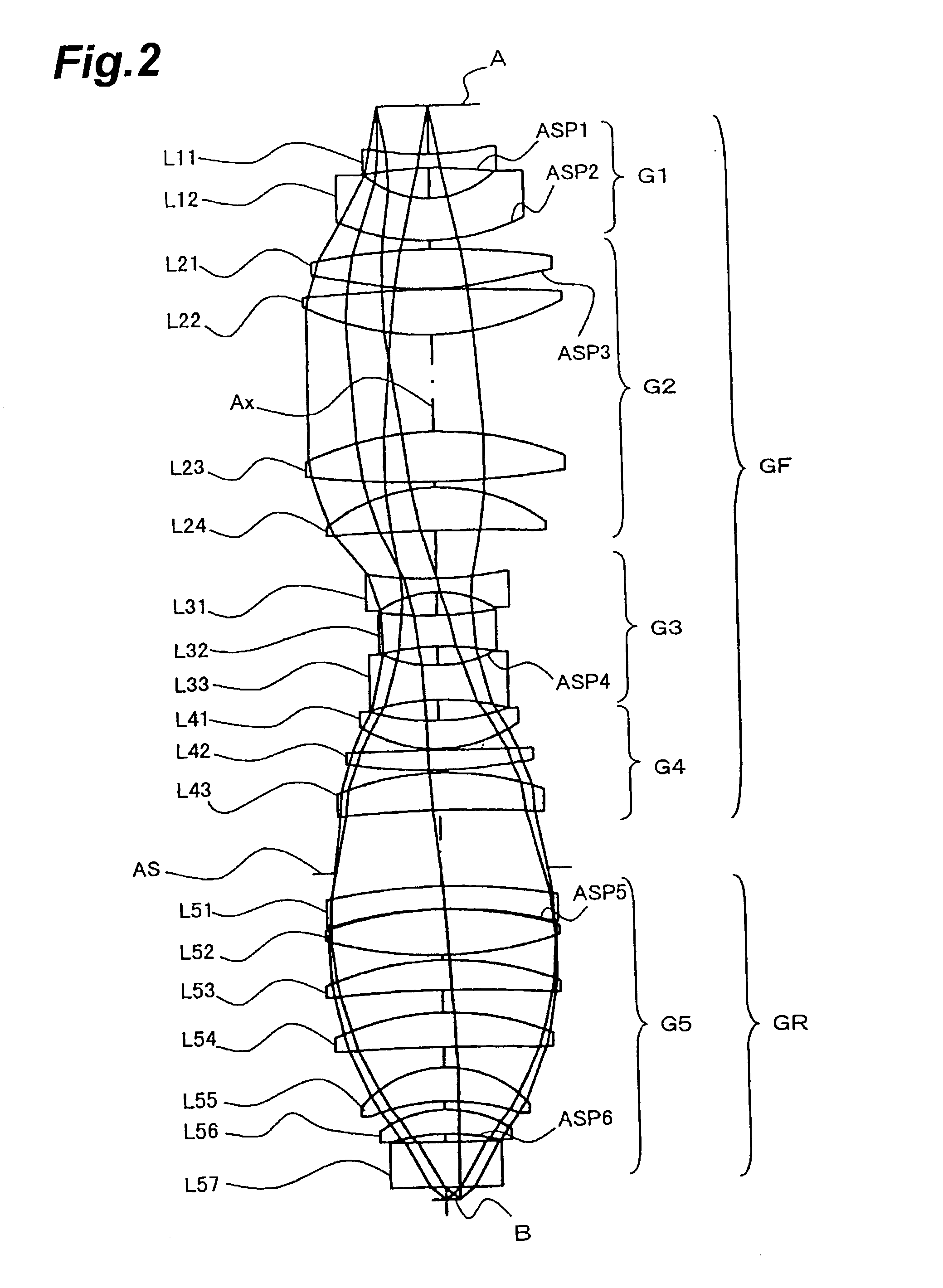
[0129] FIG. 2 is the optical path diagram of the projection optical system PL according to the

[0130] The projection optical system PL of the second embodiment uses the wavelength of 193.306 nm supplied from the band-narrowed ArF laser, as a reference wavelength and implements correction for chromatic aberration in the range of the wavelength band .+-.0.4 pm for the reference wavelength. In the second embodiment, the radiation-transmitting refractors in the projection optical system PL are made of silica glass (synthetic quartz) and fluorite.

[0131] As shown in FIG. 2, the projection optical system PL of the second embodiment has the front lens unit GF of the positive refracting power, the aperture stop AS, and the rear lens unit GR of the positive refracting power in the order named from the first surface A side. According to another grouping, the projection optical system PL of the first embodiment has the negative, first lens unit G1, the positive, second lens unit G2, the negative...

##table 1 first embodiment (fig.1)

1TABLE 1 First Embodiment (FIG. 1) d0 = 40.6446 (mm) WD = 10.8134 (mm) .vertline. .beta. .vertline. = 1 / 4 NA = 0.75 .O slashed. = 23 (mm) Radius of Surface curvature distance Aspheric (mm) (mm) Glass surface Lens 1: -446.6132 12.0000 CaF.sub.2 ASP1 L11 2: 554.7232 22.5800 3: -92.3259 46.8618 CaF.sub.2 L12 4: -6695.3973 1.1105 ASP2 5: 3832.9930 50.0000 CaF.sub.2 L21 6: -179.0867 2.1599 7: 552.3099 44.4615 CaF.sub.2 L22 8: -337.8904 72.3130 9: 416.2197 34.5857 CaF.sub.2 L23 10: -885.0528 1.0000 11: 179.8393 45.7388 CaF.sub.2 ASP3 L24 12: -3356.1983 59.3145 13: -4096.8404 12.0000 CaF.sub.2 L31 14: 160.6568 14.5833 15: -317.8664 12.0000 CaF.sub.2 L32 16: 146.7839 35.8889 17: -96.9946 12.8163 CaF.sub.2 L33 18: 190.5253 13.5021 ASP4 19: -335.6495 50.0000 CaF.sub.2 L41 20: -220.3094 1.0000 21: -2196.6594 26.1615 CaF.sub.2 L42 22: -200.6039 62.7317 23: 245.0000 38.2977 CaF.sub.2 L43 24: -522.0290 1.0000 25: .infin. 17.3237 AS 26: -268.6720 20.2571 CaF.sub.2 L51 27: 312.7719 6.2767 ASP5 28: ...


PUM


Abstract

A dioptric projection optical system for imaging a reduced image of a pattern on a first surface onto a second surface using radiation-transmitting refractors. The projection optical system has a front lens unit of a positive refracting power and a rear lens unit of a positive refracting power. An aperture stop is located in the vicinity of a rear focal point of the front lens unit.

Description

TECHNICAL FIELD[0001] The present invention relates to projection exposure apparatus and methods used in fabrication of microdevices, for example, such as semiconductor integrated circuits, imaging devices including CCDs and the like, liquid crystal displays, or thin-film magnetic heads by the lithography technology, and to projection optical systems suitably applicable to such projection exposure apparatus. The present invention also relates to methods of fabricating the foregoing projection exposure apparatus and projection optical systems.BACKGROUND ART[0002] As the circuit patterns for such microdevices as the semiconductor integrated circuits and others are becoming finer and finer in recent years, the wavelengths of illumination light(radiation) for exposure (exposure light(radiation)) used in the exposure apparatus such as steppers and the like have been decreasing toward shorter wavelengths year after year. Namely, as the exposure light, KrF excimer laser light (wavelength: ...

Claims


Application Information

Patent Timeline
IPC IPC(8): G02B13/14G02B13/18G02B13/22G02B13/24G03F7/20
CPCG02B13/143G02B13/18G02B13/22G03F7/70958G03F7/70241G03F7/70741G03F7/70883G02B13/24H01L21/027
Inventor OMURA, YASUHIRO
Owner NIKON CORP
Why Eureka
Try Eureka