Projection unit for a head-up display

a projection unit and display technology, applied in the field of lensless projection units for head-up displays, can solve the problems of large installation space, difficult to meet requirements especially for passenger vehicles, and difficult arrangement, so as to minimize optical transmission length, optimize image quality, and lengthen transmission length

Inactive Publication Date: 2006-10-19
CARL ZEISS JENA GMBH
View PDF10 Cites 37 Cited by
  • Summary
  • Abstract
  • Description
  • Claims
  • Application Information

AI Technical Summary

Benefits of technology

[0009] Therefore, it is the primary object of the invention to provide an optical arrangement for a head-up display in which the installation space is optimized. Optimization can consist in minimizing the optical transmission length and, therefore, the installation space and in lengthening the transmission length. This is advantageous, for example, when additional elements (e.g., shutters) are to be installed. The degrees of freedom for the dimensioning of the head-up display must be limited as little as possible. The image quality must be optimized by keeping the image distortion to a minimum.

Problems solved by technology

The arrangement requires a relatively large installation space which is not available particularly for applications in passenger vehicles or aircraft.
In practice, it has been shown that the use of concave and / or plane mirrors requires substantial installation space so that requirements particularly for applications in passenger vehicles can be satisfied only with great difficulty.
Further, the use of concave or plane mirrors for imaging over a curved windshield causes problems because a highly distorted image results.

Method used


Image

  • Projection unit for a head-up display
  • Projection unit for a head-up display
  • Projection unit for a head-up display

Examples


Embodiment Construction

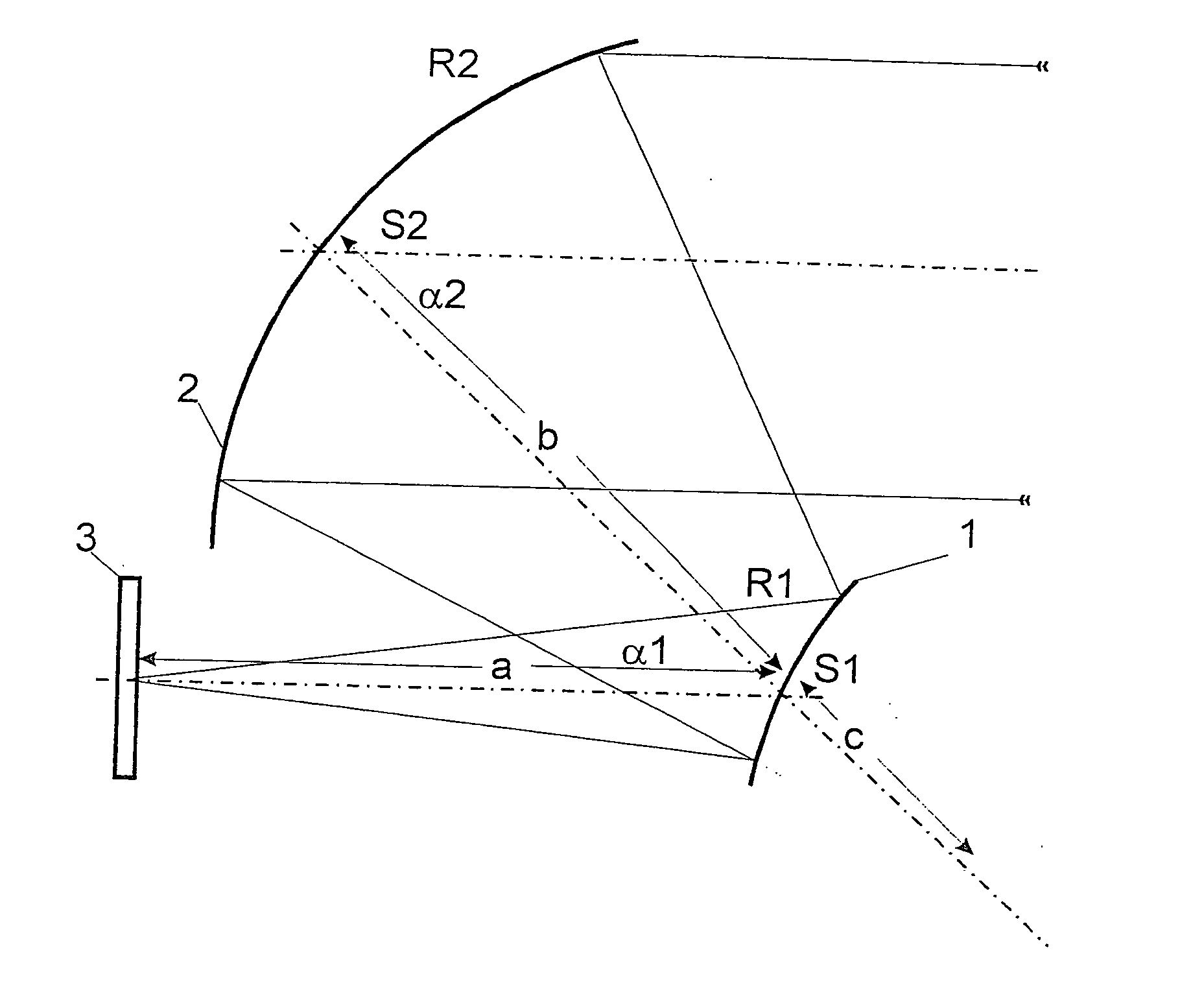
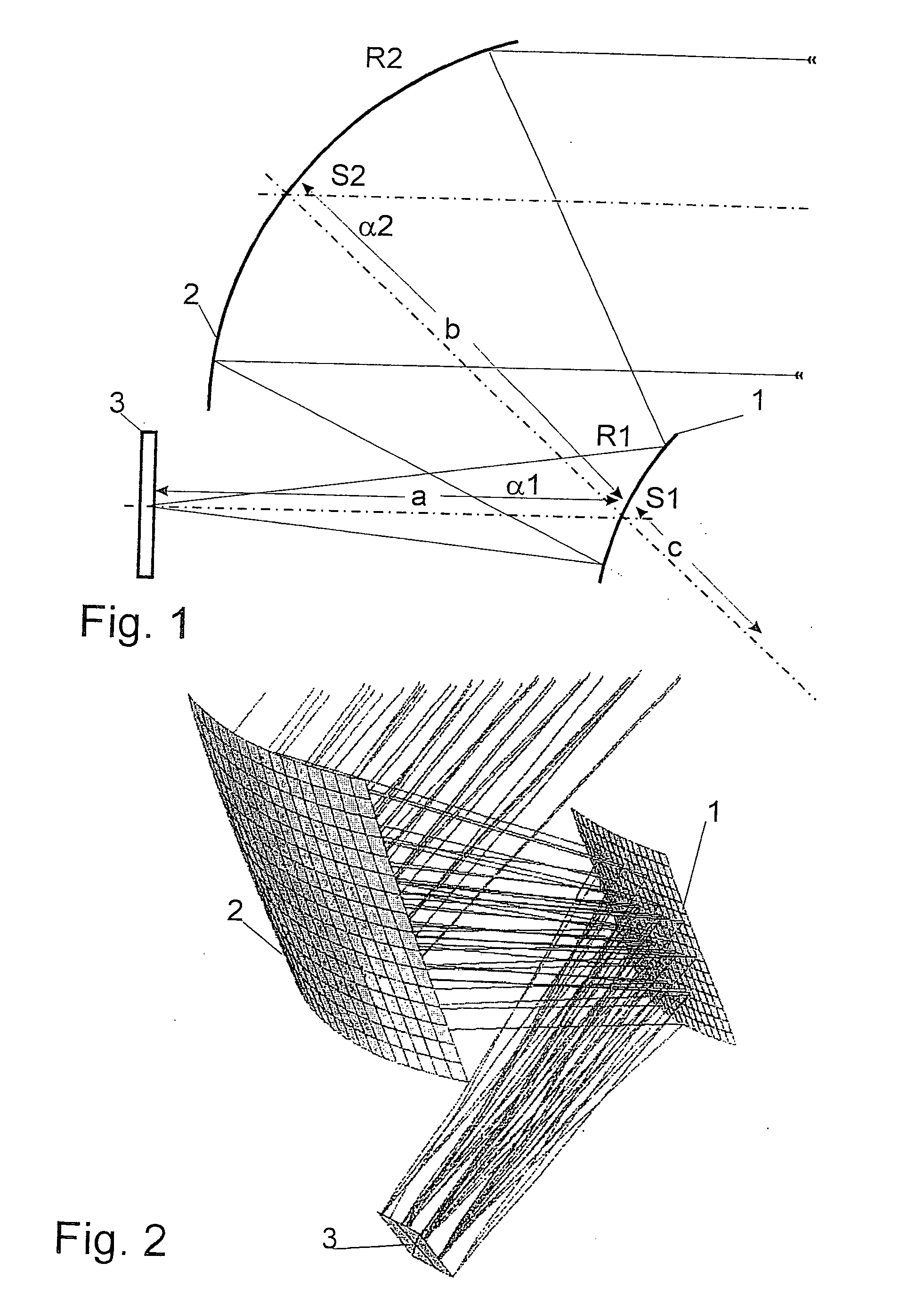
[0021]FIG. 1 is a schematic illustration showing the construction of an optical system for a head-up display. An image generator 3 is arranged at a distance a in front of a first mirror 1 which has a convex curvature with a radius R1. This first mirror folds the beam path at an angle α1. A second mirror 2 having a concave curvature with radius R2 is arranged at a distance b from the first mirror 1. The second mirror folds the beam path at an angle α2. The image generator can comprise, for example, a lamp, a laser, or LEDs as light source and can be a DLP, LCOS or LCD type, for example. However, the image generator can also generate light itself and can be, e.g., a plasma panel.

[0022]FIG. 2 shows the beam path of the arrangement according to FIG. 1.

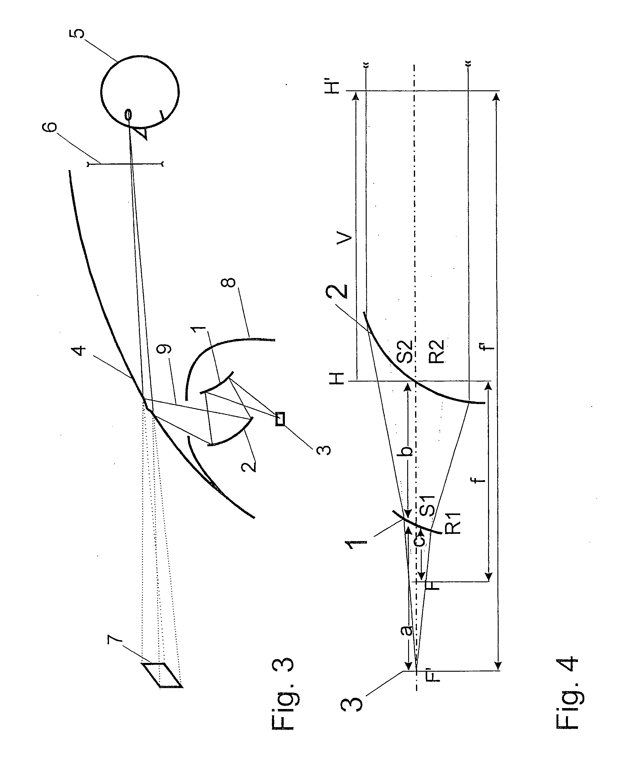
[0023]FIG. 3 shows the basic construction of the head-up display in a vehicle. The image generator 3 is arranged with the associated imaging optics inside a dashboard scoop 8. There is an opening in the dashboard scoop 8 from which the p...


PUM


Abstract

The invention is directed to a projection unit for a head-up display comprising an image generator and a first mirror and second mirror for optical imaging which are arranged in a housing one after the other in the light propagation direction in such a way that the beam path is folded twice. It is wherein one of the mirrors has a light-scattering surface shape, the other mirror h/as a light-collecting surface shape, and the two mirrors combined have a common focal point on the image generator.

Description

CROSS-REFERENCE TO RELATED APPLICATION [0001] This application claims priority of German Application No. 10 2005 017 207.5, filed Apr. 14, 2005, the complete disclosure of which is hereby incorporated by reference. BACKGROUND OF THE INVENTION [0002] a) Field of the Invention [0003] The invention is directed to a lensless projection unit for a head-up display comprising an image generator and a first mirror and second mirror for optical imaging which are arranged in a housing one after the other in the light propagation direction in such a way that the beam path is folded twice. [0004] b) Description of the Related Art [0005] EP 0 450 553 B1 describes a display device which is installed in a motor vehicle. A device of this kind is also known as a head-up display. The device uses an image generator, two reflection parts and the windshield as a reflector. Both of the reflection parts have a magnifying effect; that is, they have a concave shape. Their focal lengths are selected in such ...

Claims


Application Information

Patent Timeline
Patent Type & Authority Applications(United States)
IPC IPC(8): G02B23/00G02B21/00
CPCG02B17/0615G02B17/0605
Inventor DOBSCHAL, HANS-JUERGENTROELLSCH, ARNEJAHN, DIRK
Owner CARL ZEISS JENA GMBH
Why Eureka
Try Eureka