Oil-path-carried leaf-valve type variable cam-shaft timing phase meter

A reed valve and phaser technology, applied in the field of vane type variable cam timing devices

Inactive Publication Date: 2004-06-30
BORG WAMER CORP
View PDF0 Cites 11 Cited by
  • Summary
  • Abstract
  • Description
  • Claims
  • Application Information

AI Technical Summary

Problems solved by technology

All reed valves are located on the reed plate

Method used


Image

  • Oil-path-carried leaf-valve type variable cam-shaft timing phase meter
  • Oil-path-carried leaf-valve type variable cam-shaft timing phase meter
  • Oil-path-carried leaf-valve type variable cam-shaft timing phase meter

Examples


Embodiment Construction

[0018] "Phaser" refers to any engine element that enables the camshaft to turn independently of the crankshaft.

[0019] The invention overcomes various defects of the check valve in the prior art. One of the advantages of the present invention is that the reed valve does not have to be opened very much in order to obtain sufficient oil flow, since the entire area of ​​the reed valve opens upwards allowing a larger flow volume. In addition, prior art check valves are seated on a flat surface, requiring force to open the valve. In contrast, the reed valve of the present invention acts like a zipper, opening more easily and quickly. Furthermore, the fields of application in which the reed valve can be assembled are increased. Replacing the multi-element prior art check valve with a single reed valve results in a lower cost check valve.

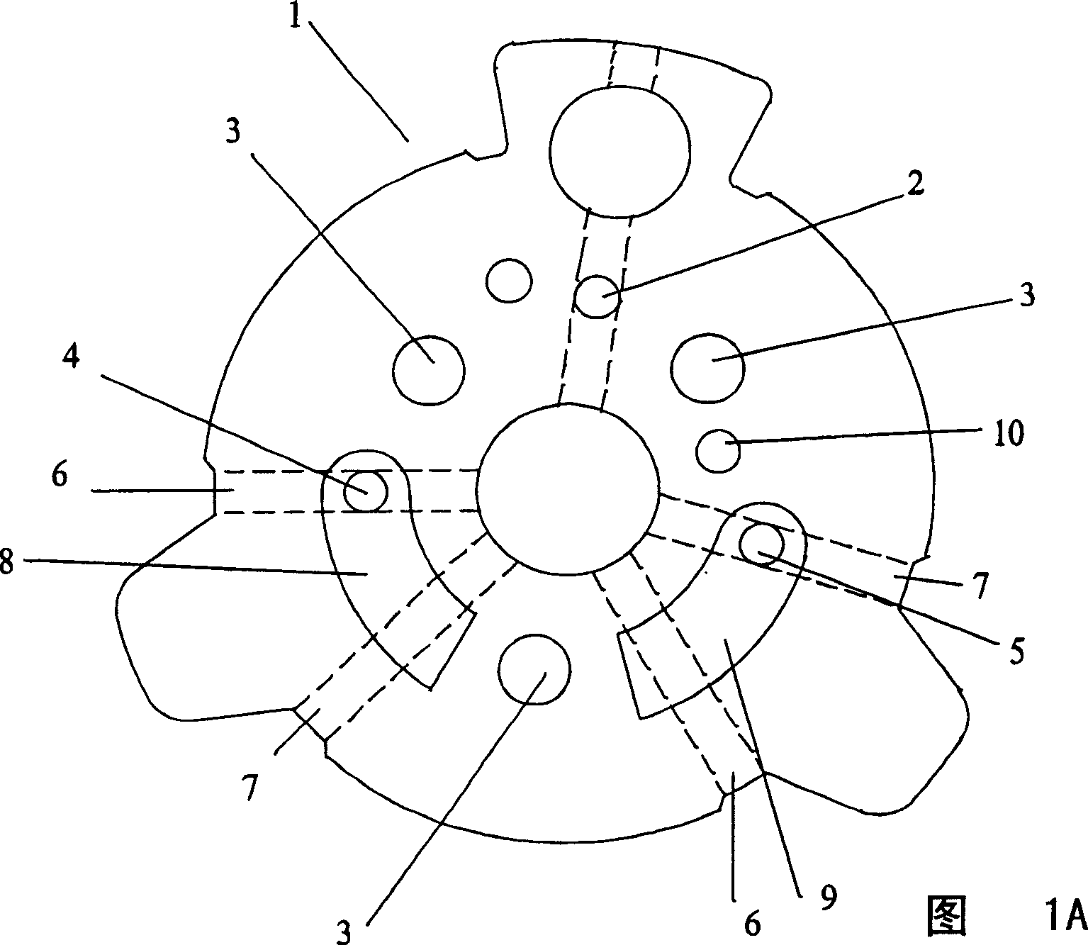
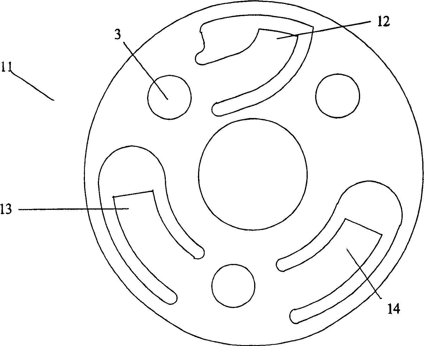
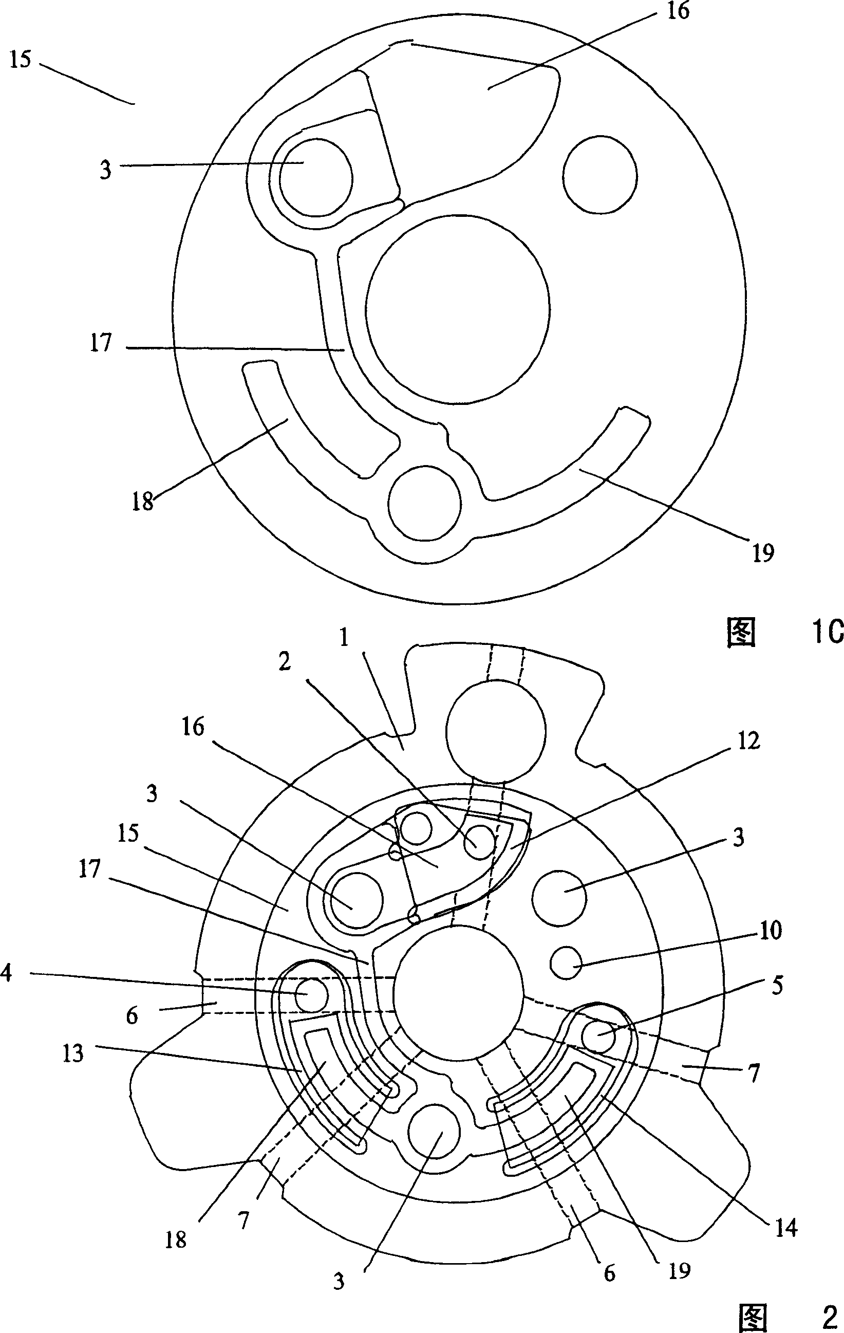
[0020] Figures 1A-1C show the rotor (1), reed plate (11) and separator (15). These three elements are combined to form Figure 2. As shown ...


PUM


Abstract

The phaser of the present invention includes a reed plate. The reed plate has reed valves, which control the flow of hydraulic fluid. The reed valves are all inclusive on the reed plate. Worm trails in the surface of the parts sandwiching the reed plate direct the flow to and from the reed valves.

Description

【Technical field】 [0001] related application [0002] This application claims the invention of Provisional Patent Application 60 / 374,599, published April 22, 2002, entitled "Oil Reed Type Variable Cam Timing." The benefit of 35 USC §119(e) under US Provisional Application is hereby claimed, and the above application is hereby incorporated by reference into this application. [0003] The present invention relates to the field of variable camshaft timing (VCT) systems. More particularly, the present invention relates to a vane type variable cam timing device applying an oil path reed valve to the flow of hydraulic fluid. 【Background technique】 [0004] For engines with one or several camshafts, engine performance, especially idling characteristics, fuel economy, reduced emissions, or increased torque, can be improved with a variable cam timing (VCT) system. For example, the camshaft can be "retarded" to delay the closing of the intake valves for smoo...

Claims


Application Information

Patent Timeline
IPC IPC(8): F01L1/34F01L1/344F01L1/46
CPCF01L1/34F01L1/46Y10T137/7845F01L3/20
Inventor J·H·路易斯R·G·威廉森
Owner BORG WAMER CORP
Why Eureka
Try Eureka