Tapping screw

a technology of tapping screw and screw body, which is applied in the direction of screws, threaded fasteners, fastening means, etc., can solve the problems of insufficient anti-loosening effect and difficulty in reliably preventing the tapping screw from being undetectedly loosened, and achieve excellent anti-loosening effect and enhance the anti-loosening

Active Publication Date: 2015-03-24
NITTO SEIKO KO
View PDF23 Cites 6 Cited by
  • Summary
  • Abstract
  • Description
  • Claims
  • Application Information

AI Technical Summary

Benefits of technology

[0006]The tapping screw can exert not only an anti-loosening effect resulting from a portion of the workpiece being embedded into the clearance groove but also an anti-loosening effect resulting from the engaging protrusion being embedded into the portion of the workpiece that has been embedded into the clearance groove.
[0008]In the tapping screw having the above-mentioned structure, a portion of workpiece, which is compressed by the external thread when an internal thread is formed in the hole of the workpiece, is embedded into each clearance groove. Here, a larger amount of workpiece portion is embedded the side that has the smaller flank angle. Therefore, in the case where the engaging protrusion is provided on an edge of the bottom of the clearance groove that continuously extends from the flank surface having a smaller flank angle, the anti-loosening effect can be further enhanced.
[0010]In this case, portions of the workpiece that are compressed by the external thread while the internal thread is formed in the hole are embedded into the circumferential surface of the shaft part, thus further enhancing the anti-loosening effect.
[0011]A tapping screw according to the present invention exerts an excellent anti-loosening effect even when a workpiece expands, contracts or oscillates.

Problems solved by technology

However, the conventional tapping screw cannot satisfactorily exert an anti-loosening effect, so that it is difficult to reliably prevent the tapping screw from being undesirably loosened.

Method used


Image

  • Tapping screw
  • Tapping screw
  • Tapping screw

Examples


first embodiment

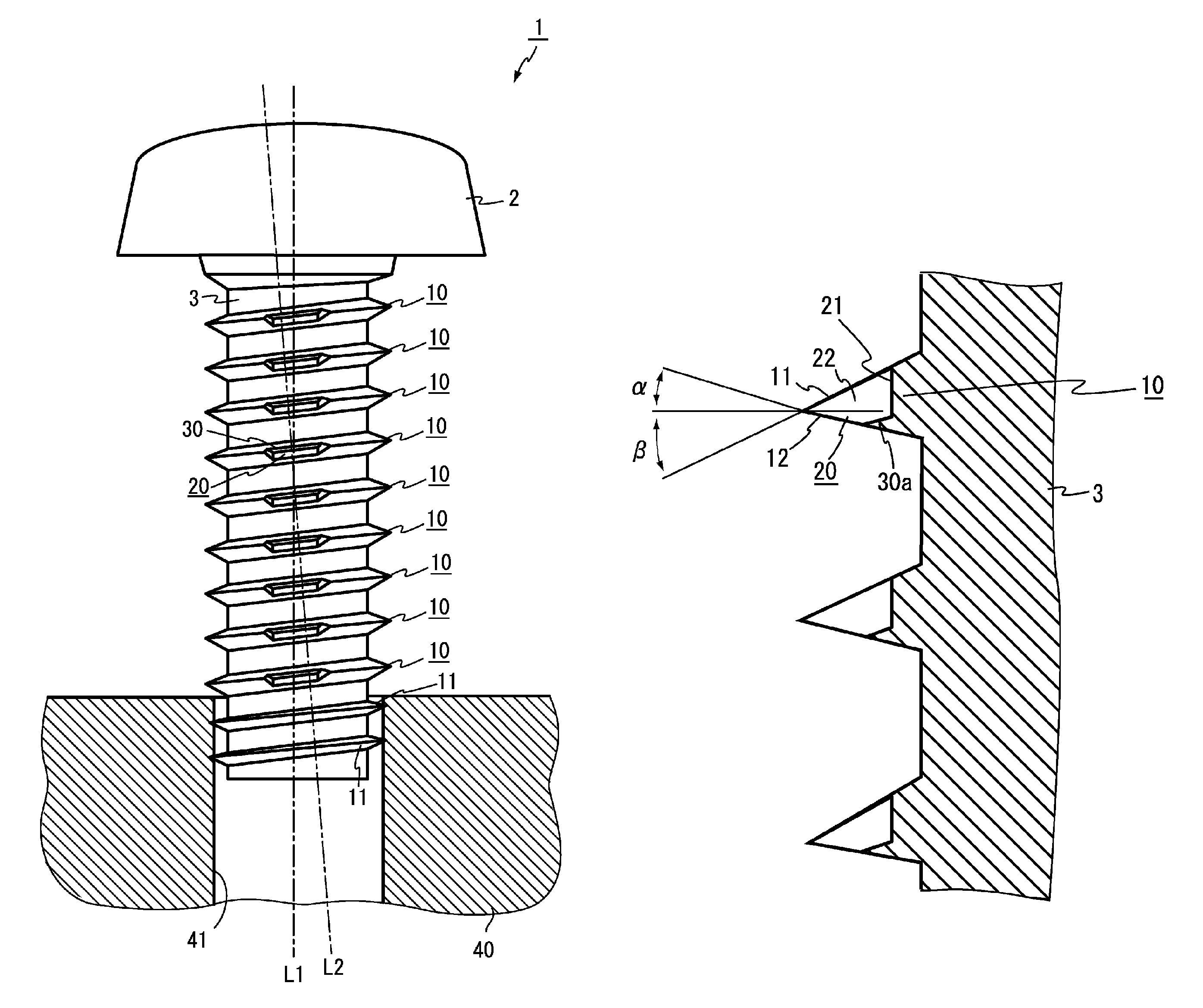
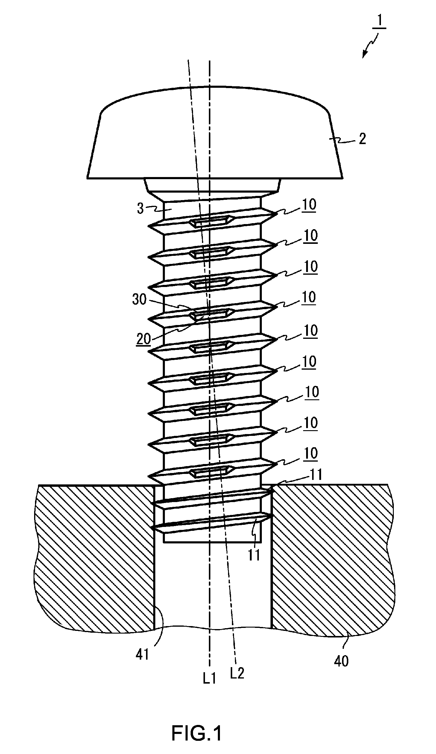
[0024]Hereinafter, the present invention will be described in detail with reference to FIGS. 1 through 4. Referring to FIG. 1, reference numeral 1 denotes a tapping screw including a head part 2 and a shaft part 3 which is integrally provided with the head part 2. For example, the tapping screw 1 is made of carbon steel. The head part 2 has in the surface thereof a drive hole (not shown) through which screw driving force is transmitted to the tapping screw 1 from a driver bit (not shown). A normal thread 10 is formed on an outer circumferential surface of the shaft part 3 that is integrally provided with the head part 2.

[0025]Having a smaller diameter than that of the normal thread 10, a guide thread 11 is provided on the outer circumferential surface of a front end of the shaft part 3 and continuously extended from the normal thread 10. The guide thread 11 has a diameter that is equal to or is slightly greater than the diameter of a hole 41 formed in a workpiece 40. As such, the ta...

second embodiment

[0031]FIGS. 5 and 6 illustrate a tapping screw 1a of the

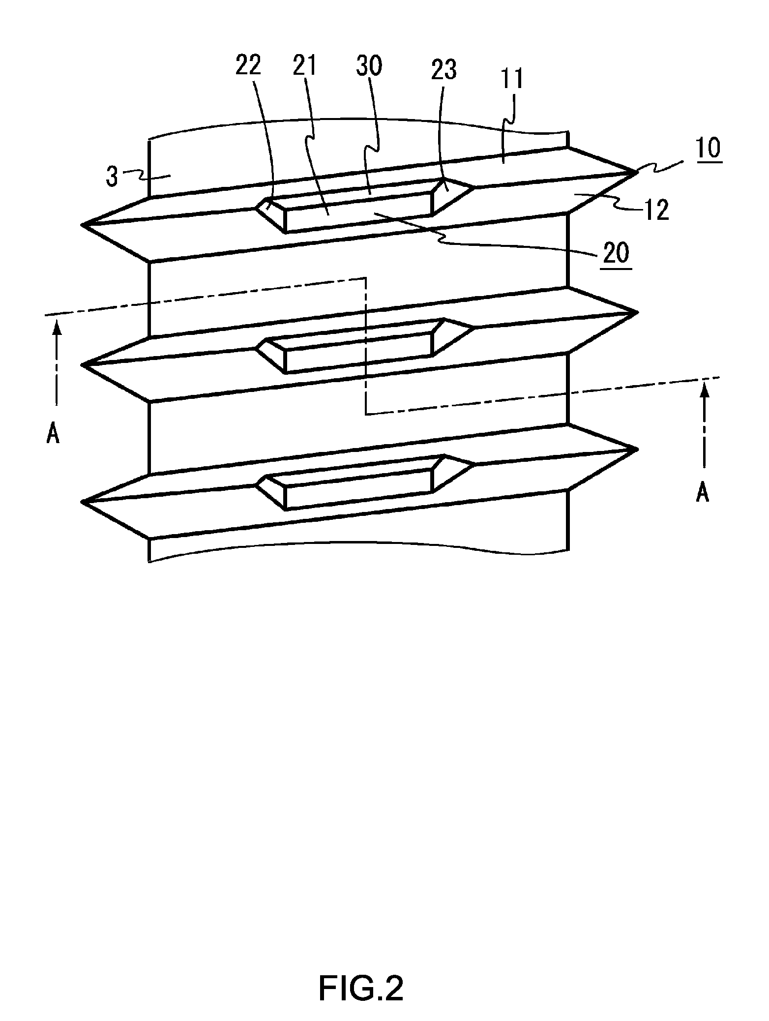
[0032]The tapping screw 1a is set such that the pressure flank angle β is larger than the leading flank angle α (β>α). Therefore, an engaging protrusion 30a is provided on an edge of the bottom 21 that continuously extends from the leading flank surface 12.

third embodiment

[0033]FIGS. 7 and 8 illustrate a tapping screw 1b of the The tapping screw 1b is set such that the pressure flank angle β is the same as the leading flank angle α (β=α). Therefore, engaging protrusions 30b and 31b are respectively provided on opposite edges of the bottom 21 that extend from the pressure flank surface 11 and the leading flank surface 12.


PUM


Abstract

Disclosed herein is a tapping screw (1) exerting an excellent anti-loosening effect with regard to a workpiece made of a soft material such as resin and an aluminum alloy. The tapping screw (1) includes a shaft part (3), and a normal thread (10) which is formed on the outer circumferential surface of the shaft part. A clearance groove (20) is formed by cutting out a portion of a ridge of the normal thread, and an engaging protrusion (30) is provided on a bottom of the clearance groove along a portion or an entirety of an edge of the bottom that continuously extends from a flank surface of the normal thread. The tapping screw (1) exerts an excellent anti-loosening effect even when a workpiece expands, contracts or oscillates because the engaging protrusions (30) are embedded into portions of the workpiece which have been embedded into the clearance grooves (20).

Description

FIELD OF THE INVENTION[0001]The present invention relates to a tapping screw which is threaded into a non-threaded hole, formed in a workpiece, while forming an internal thread in the hole.BACKGROUND OF THE INVENTION[0002]Generally, tapping screws are threaded into workpieces made of soft materials such as resin, aluminum alloys, etc. A representative example of such tapping screws was proposed in Japanese Patent No. 3290362. In this tapping screw, an external thread is spirally formed on an outer circumferential surface of a shaft part. By virtue of the external thread, the tapping screw forms an internal thread in a hole formed in a workpiece while the tapping screw is threaded into the hole. Furthermore, portions of a ridge of the external thread are cut out in the same direction as that of an axis of the tapping screw so as to form clearance grooves. Portions of the workpiece that are compressed by the external thread when the internal thread is formed, are embedded into the cle...

Claims


Application Information

Patent Timeline
Patent Type & Authority Patents(United States)
IPC IPC(8): F16B35/04F16B25/00
CPCF16B25/00F16B25/0047F16B25/0052F16B33/02F16B39/30
Inventor HAMANO, SINNICHINISHIMURA, NAOKIKOWADA, KINYAUEBA, KAZUHIRO
Owner NITTO SEIKO KO
Why Eureka
Try Eureka