Eureka AIR delivers breakthrough ideas for toughest innovation challenges, trusted by R&D personnel around the world.

Surgical instrument with pivotable implant holder

a surgical instrument and implant holder technology, applied in the field of surgical implant instruments and systems, can solve the problems of standard cage implants not being used, implants had, etc., and achieve the effect of convenient securing, locking, fixing or clamping of implants

Active Publication Date: 2015-03-24
X SPINE SYST
View PDF106 Cites 12 Cited by
  • Summary
  • Abstract
  • Description
  • Claims
  • Application Information

AI Technical Summary

Benefits of technology

[0015]Another object of an embodiment of the invention is to provide a universal joint for use in a surgical instrument wherein the universal joint is adapted to permit multiple functions, including pivoting and rotating of an implant holder, to facilitate securing, locking, fixing or clamping of an implant to the instrument.

Problems solved by technology

One problem with the prior art devices is their complexity and that they either did not permit pivoting of the implant or required multiple components to permit the implant to be pivoted and separate components to fix the implant to the instrument after the implant was pivoted to the desired position.
Another problem with some prior art devices was that the cage implant had to be custom fit to the holder and standard cage implants could not be used.

Method used


Image

  • Surgical instrument with pivotable implant holder
  • Surgical instrument with pivotable implant holder
  • Surgical instrument with pivotable implant holder

Examples


Embodiment Construction

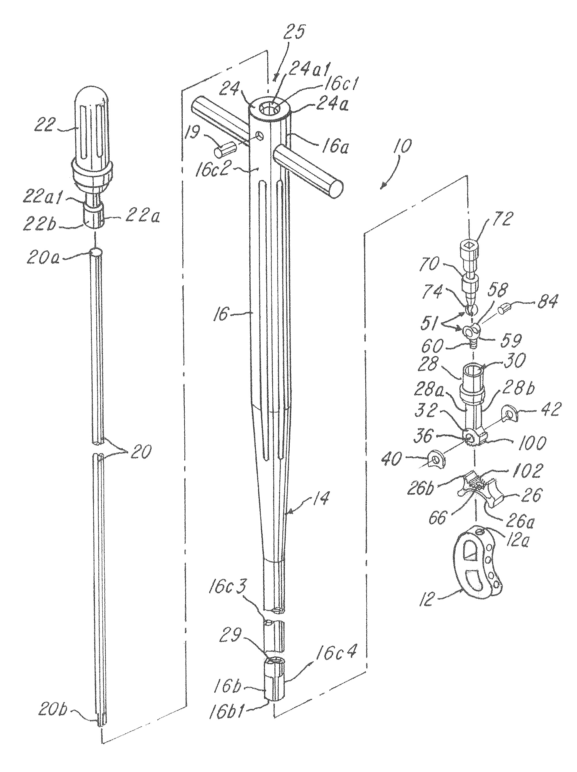
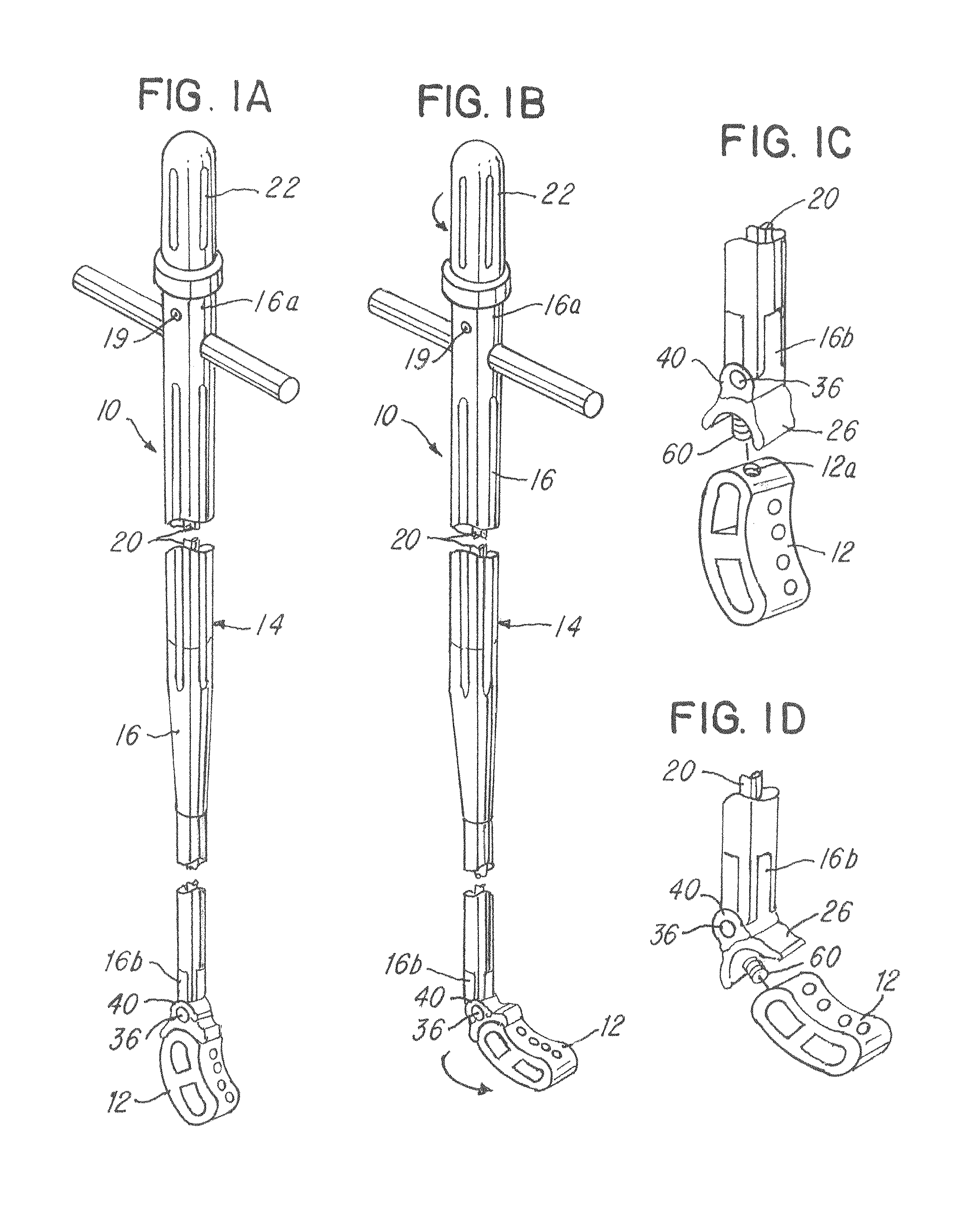
[0031]Referring now to FIGS. 1-9D, a surgical instrument and system 10 are shown. The surgical instrument and system 10 comprises an implant 12 and a surgical instrument 14 for inserting the implant 12 into a patient. In one illustrative embodiment, the implant 12 is an intervertebral cage and the surgical instrument 14 adapted to insert the intervertebral cage in a disk area (not shown) between a pair of adjacent vertebrae (not shown). In general, one embodiment enables or permits the implant 12 to be mounted on the instrument (e.g., as shown in FIGS. 1A and 1C) and pivoted or moved to a pivoted or desired position (e.g., as shown in FIGS. 1B and 1D). The invention permits loosening and tightening of the implant 12 to the instrument before, during, after and through such pivotal movement.

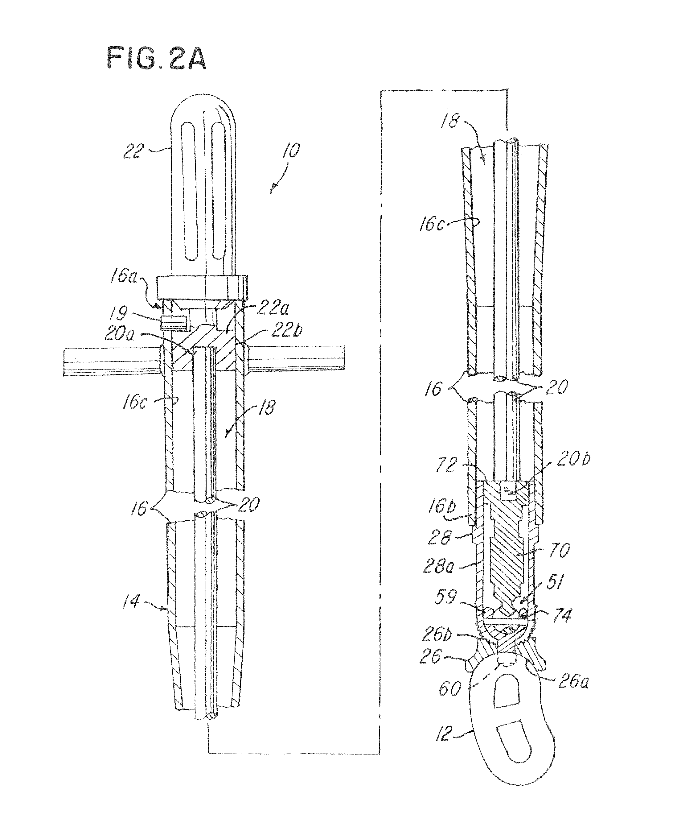
[0032]In the illustration being described, the surgical instrument 14 comprises a housing 16 which in one illustrative embodiment is tubular and has a first end 16a and a second end 16b. The housin...


PUM


Abstract

A surgical instrument for inserting an implant is shown. The instrument has a housing having a first end and a second end, a rotatable drive member having an elongated member comprising a grip that is associated with the first end, an implant holder having a securing member that extends through the second end and that is adapted to receive and hold the implant. A universal joint couples the implant holder and the elongated member and is adapted to permit a user to rotatably drive the implant holder when the implant holder is in a pivoted position.

Description

BACKGROUND OF THE INVENTION[0001]1. Field of the Invention[0002]This invention relates to a surgical implant instrument and system and, more particularly, to an instrument and system having an implant holder having a joint that is adapted to permit the implant holder to be loosened, moved or pivoted to a desired position and tightened before, during and after such movement or pivoting.[0003]2. Background of the Invention[0004]In the past, surgical instruments were provided for applying or inserting implants between adjacent vertebrae in a vertebral column. The implant was positioned or fixed at the end of the instrument usually in a fixed or rigidly connected position.[0005]In some prior art instruments, the tool permitted a variable adjustable alignment of the implant in relation to the instrument. For example, some instruments had a non-pivotable threaded screw that screwed directly into the implant and held the implant in a fixed position at the end of the instrument. In one prio...

Claims


Application Information

Patent Timeline
Patent Type & Authority Patents(United States)
IPC IPC(8): A61B17/70A61B17/88A61F2/30A61F2/44A61F2/46
CPCA61F2/4465A61F2/4611A61B17/8872A61F2002/30538A61F2002/30797A61F2002/4623A61F2002/4627A61F2002/4628A61F2002/4629A61F2/4603
Inventor KIRSCHMAN, DAVID LOUIS
Owner X SPINE SYST
Why Eureka
Eureka Blog
Learn More