
Image scanning device with improved dew condensation detection and correction

a scanning device and condensation detection technology, applied in the field of image scanning apparatuses, can solve the problems of image being scanned in dark and low quality, falling reflectance, transmittance, etc., and wasting electric power

Inactive Publication Date: 2015-03-24
KYOCERA DOCUMENT SOLUTIONS INC
View PDF10 Cites 1 Cited by
  • Summary
  • Abstract
  • Description
  • Claims
  • Application Information

AI Technical Summary

Benefits of technology

Accurately detects condensation and activates heating only when needed, improving image quality and reducing energy waste by ensuring precise control over heating processes.

Problems solved by technology

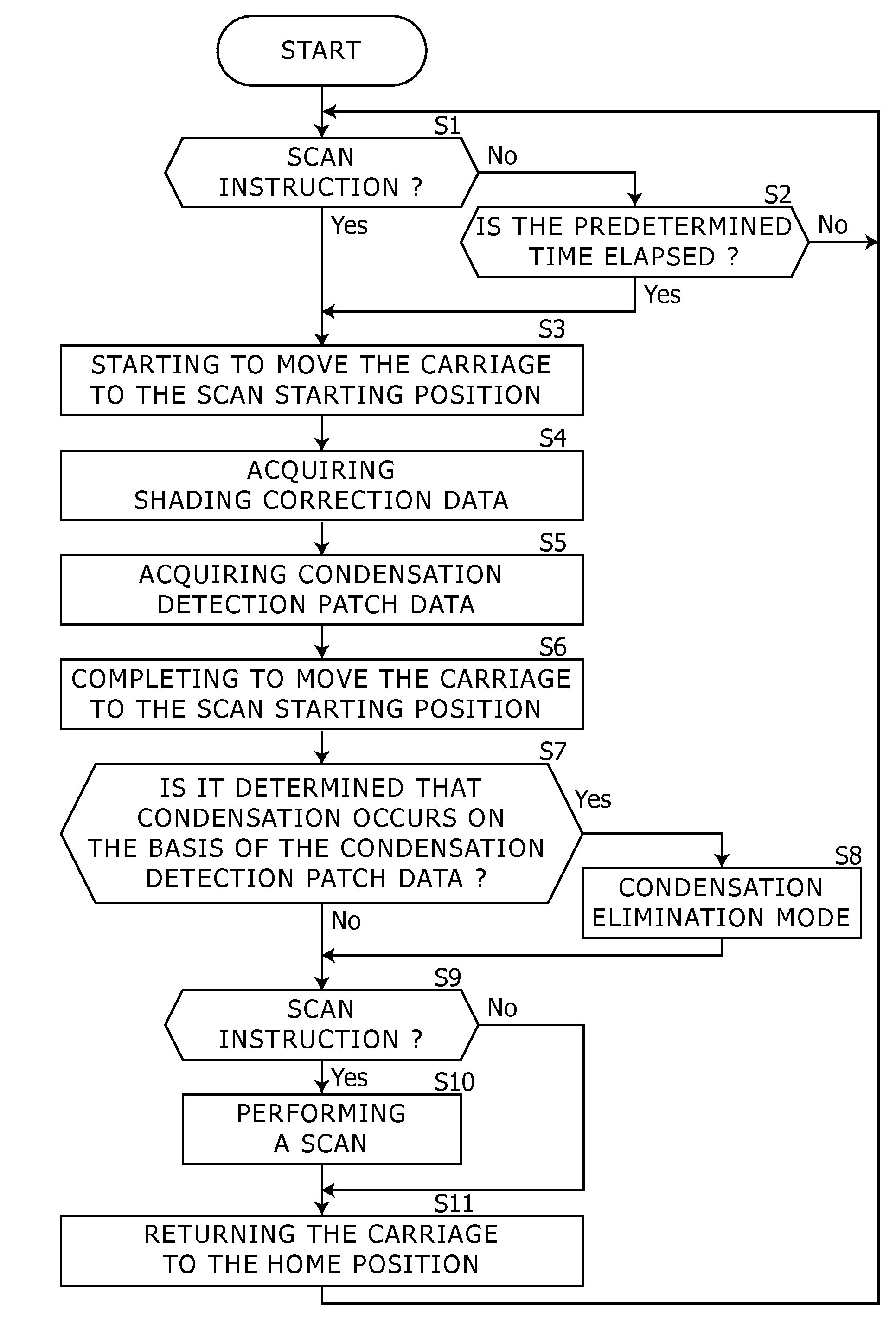
When an image scanning apparatus is used in a low temperature environment such as a cold region or an early morning in winter, condensation sometimes occurs on a surface of an optical unit such as a mirror and results in a fall in reflectance, transmittance, or the like, and consequently, an image is scanned darkly and in a low quality.
Consequently, it wastes electric power.
However, in the case that it is estimated whether condensation occurs or not in the aforementioned manner, for example, if condensation occurred when the last shading data on yesterday was obtained, then condensation that currently occurs may not be detected.

Method used


Image

  • Image scanning device with improved dew condensation detection and correction
  • Image scanning device with improved dew condensation detection and correction
  • Image scanning device with improved dew condensation detection and correction

Examples


Embodiment Construction

[0015]Hereinafter, embodiments according to aspects of the present disclosure will be explained with reference to drawings.

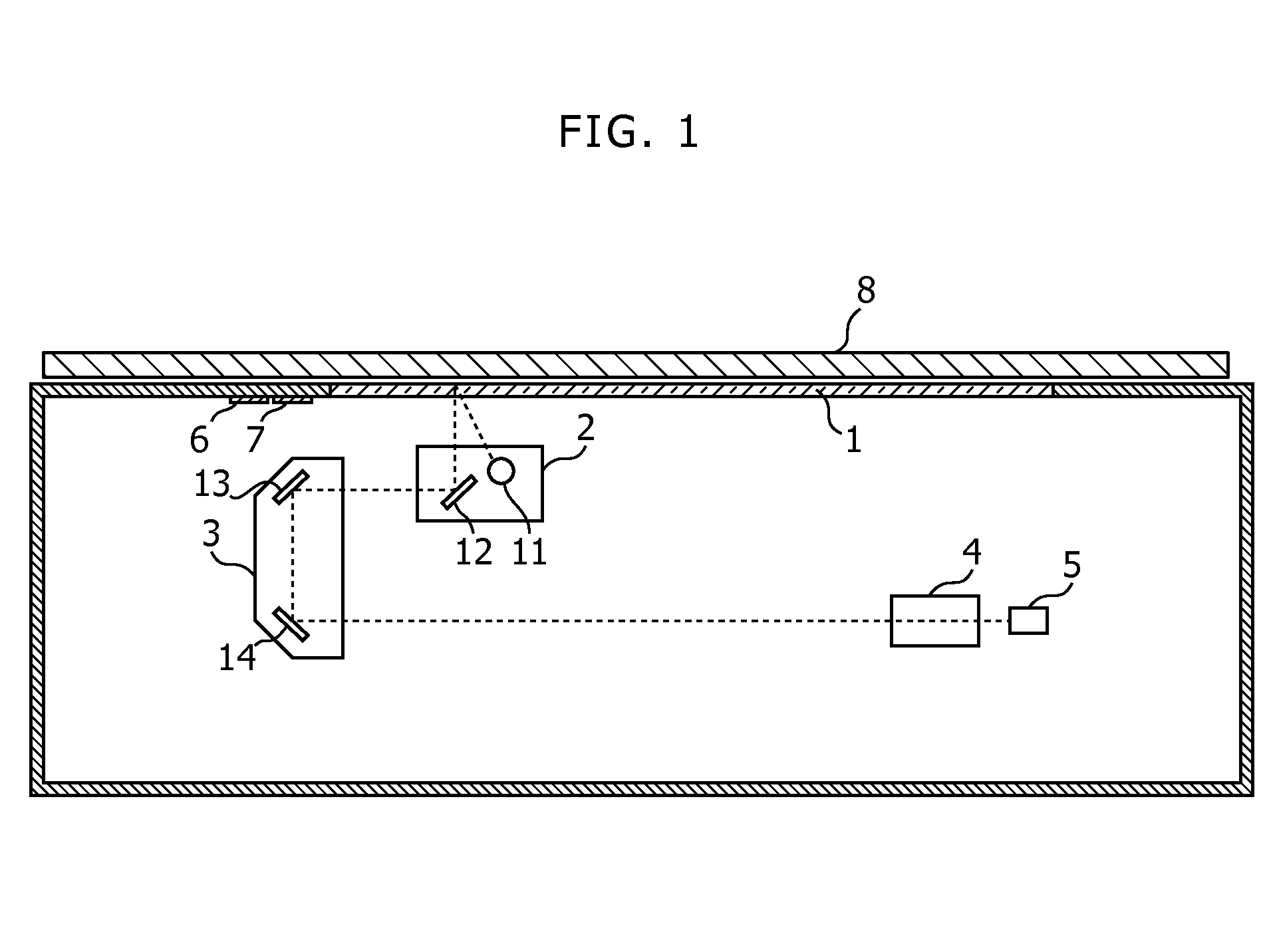
[0016]FIG. 1 shows a side view of an internal configuration of an image scanning apparatus in this disclosure. The image scanning apparatus shown in FIG. 1 is an apparatus such as scanner, copier, or multi-function peripheral.

[0017]In FIG. 1, a contact glass 1 is disposed on a top surface of a body of the image scanning apparatus, and a document is put on the contact glass 1 when a document image is scanned from the document.

[0018]A carriage 2 is capable of moving in the secondary scanning direction with an unshown driving source. The carriage 2 includes a light source 11 and a mirror 12. The light source 11 is arranged along the primary scanning direction, and emits light, for example, with pluralities of aligned light emitting diodes. The light emitted from the light source 11 reflects at positions corresponding to a position of the carriage 2, such as a docum...


PUM

PropertyMeasurementUnit
reflectancesaaaaaaaaaa
reflectanceaaaaaaaaaa
temperatureaaaaaaaaaa

Abstract

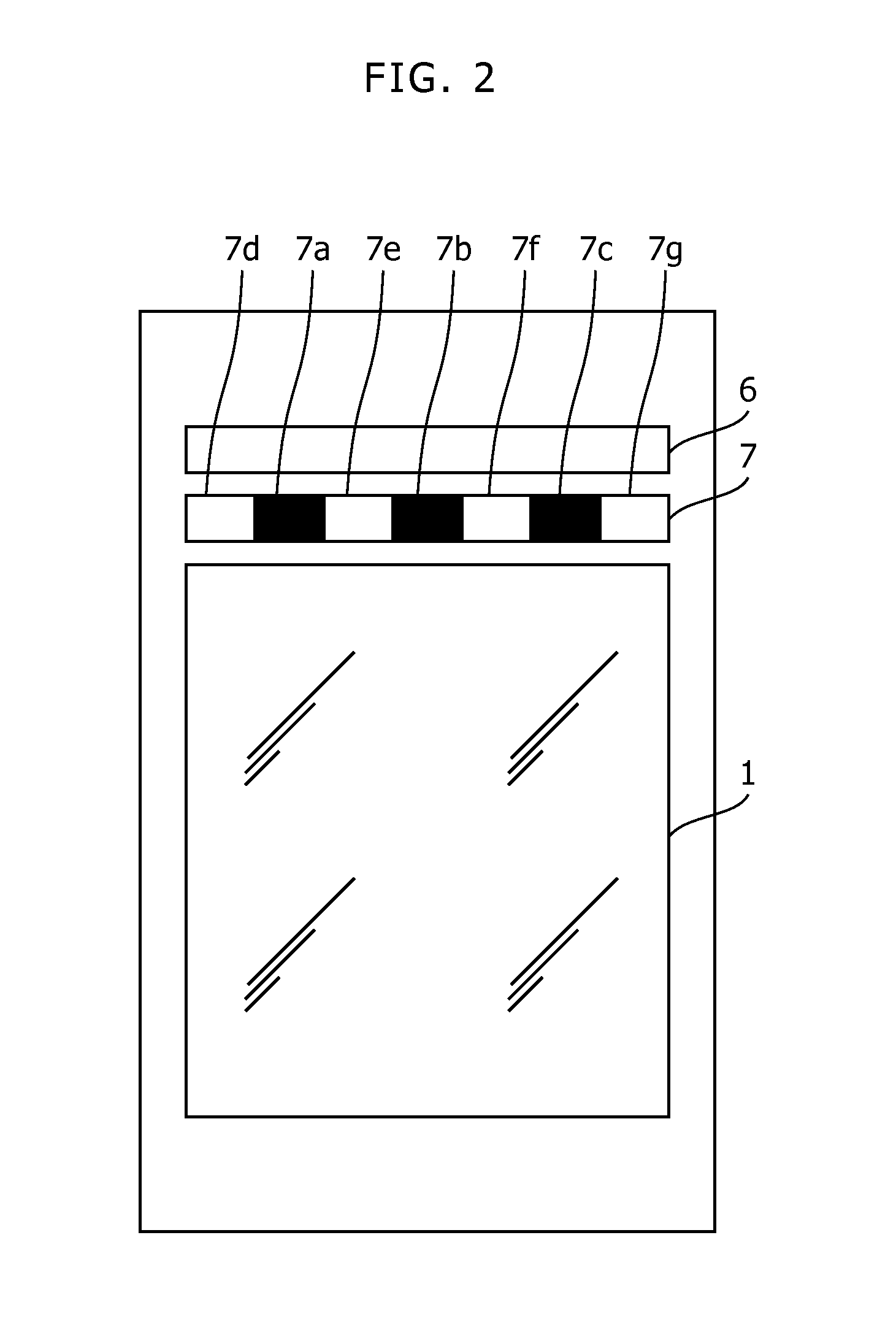
In the aforementioned image scanning apparatus of this embodiment, a condensation detection patch includes pluralities of patch areas with different reflectances arranged adjacently. A data acquiring unit acquires measurement values of the condensation detection patch by an image sensor as condensation detection patch data. A condensation determining unit determines whether condensation occurs or not on the basis of the condensation detection patch data corresponding to one with a low reflectance of two patch areas arranged adjacently in the patch areas.

Description

CROSS-REFERENCE TO RELATED APPLICATIONS[0001]This application relates to and claims priority rights from Japanese Patent Application No. 2011-163616, filed on Jul. 26, 2011, the entire disclosures of which are hereby incorporated by reference herein.BACKGROUND OF THE INVENTION[0002]1. Field of the Invention[0003]The present invention relates to image scanning apparatuses.[0004]2. Description of the Related Art[0005]When an image scanning apparatus is used in a low temperature environment such as a cold region or an early morning in winter, condensation sometimes occurs on a surface of an optical unit such as a mirror and results in a fall in reflectance, transmittance, or the like, and consequently, an image is scanned darkly and in a low quality. Therefore, an image scanning apparatus includes a heater to prevent from condensation, and performs heating with the heater to warm-up before an image scan.[0006]For example, a known mechanism to prevent from condensation automatically per...

Claims


Application Information

Patent Timeline
Patent Type & Authority Patents(United States)
IPC IPC(8): G03F3/08G03G15/00H04N1/00H04N1/03H04N1/10
CPCH04N1/00992G03G15/55H04N1/03H04N1/1013G03G2215/00776
Inventor YAMAUCHI, HIRONORI
Owner KYOCERA DOCUMENT SOLUTIONS INC
Learn More