Inter-vehicle control apparatus

a control apparatus and vehicle technology, applied in vehicle position/course/altitude control, process and machine control, instruments, etc., can solve the problems of generating required sudden deceleration of the own vehicle, unnecessarily large degree of deceleration, and driver discomfort, so as to reduce the risk of collision determined by the determining uni

Active Publication Date: 2016-12-06
DENSO CORP
View PDF6 Cites 0 Cited by
  • Summary
  • Abstract
  • Description
  • Claims
  • Application Information

AI Technical Summary

Benefits of technology

[0010]It is thus desired to provide an inter-vehicle control apparatus that is capable of actualizing deceleration behavior of a vehicle that is suitable for feeling of a driver.
[0015]When the detection unit detects the above-described events, the limiting unit sets the limit value of the target jerk to a value based on the risk of collision determined by the determining unit. As a result, the change in deceleration of the own vehicle can be kept lower as the determined risk of collision decreases.
[0016]In the inter-vehicle control apparatus of the exemplary embodiment, the target jerk is provided with a limit value, as described above. Thus, even when a new preceding vehicle cuts in ahead of the own vehicle and the actual inter-vehicle physical quantity discontinuously changes, sudden deceleration caused by a discrepancy between the actual inter-vehicle physical quantity and the target inter-vehicle physical quantity can be suppressed.
[0019]As a result of the inter-vehicle control apparatus being configured in this way, sudden deceleration caused by the occurrence of the above-described events at an early stage of the events can be suppressed. In addition, the actual inter-vehicle physical quantity can be changed to the target inter-vehicle physical quantity at a speed based on the risk of collision felt by the driver.
[0020]Furthermore, when the at least one of the first event and the second event is detected, the limiting unit may set the upper limit value of the deceleration gradient such that: (i) the upper limit value gradually increases from an initial value to a standard value over time; and (ii) an amount of time until the upper limit value of the deceleration gradient changes from the initial value to the standard value becomes longer as the risk of collision decreases. As a result of a technique for changing the limit value of the target jerk in this way, the limit value can be appropriately adjusted by a simple process. Deceleration behavior preferable to the feeling of the driver can be actualized.

Problems solved by technology

For example, when a new preceding vehicle cuts in ahead of the own vehicle and the inter-vehicle distance discontinuously changes, an unnecessarily large degree of deceleration may occur.
For example, an excessively large amount of deceleration, which is disproportionate to the risk of collision with the preceding vehicle felt by the driver, may occur, thereby causing the driver some discomfort.
When the driver feels a high risk of collision, the required sudden deceleration of the own vehicle is generated.

Method used


Image

  • Inter-vehicle control apparatus
  • Inter-vehicle control apparatus
  • Inter-vehicle control apparatus

Examples


Embodiment Construction

[0029]An example of the present invention will hereinafter be described with reference to the drawings.

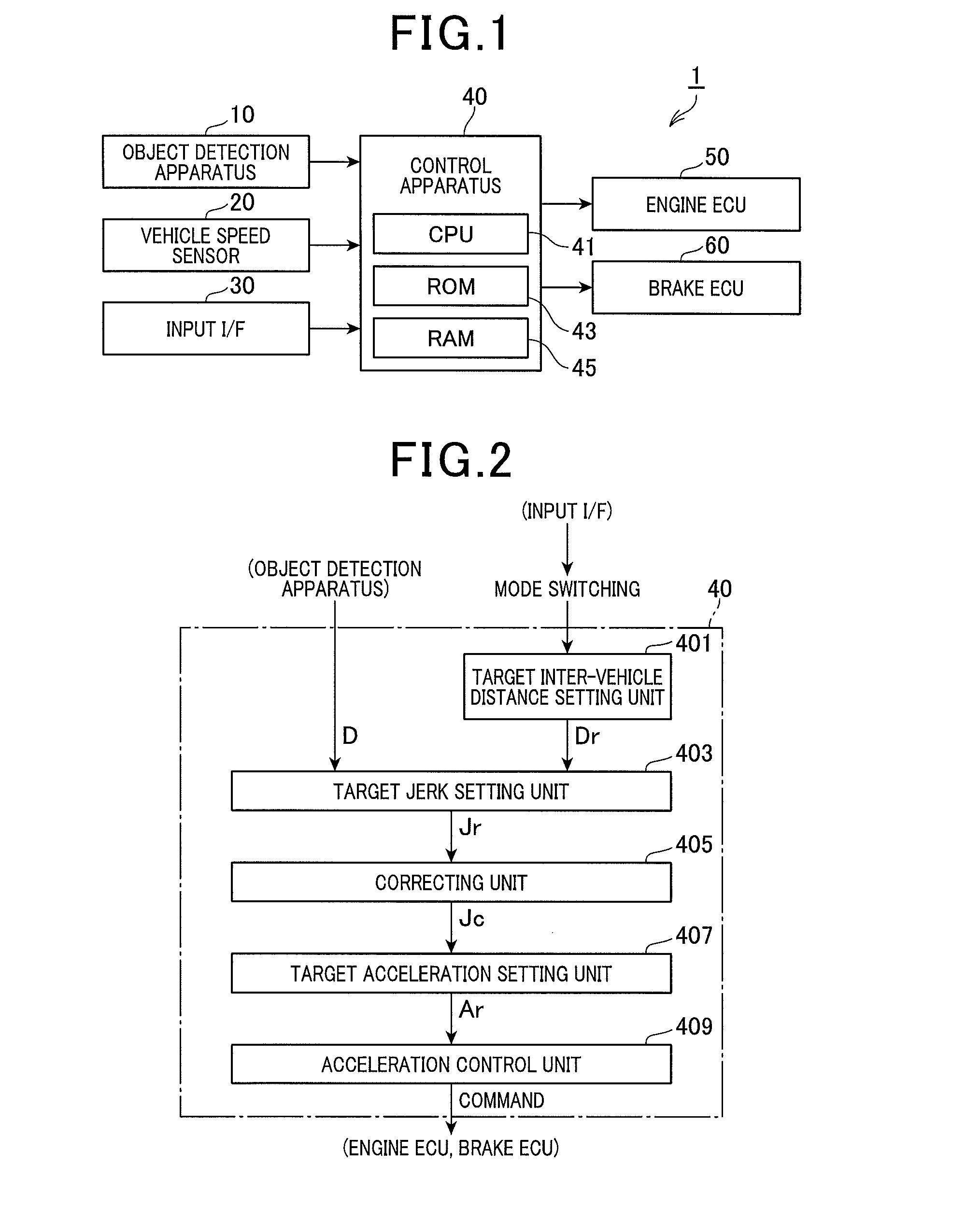
[0030]An on-board system 1 of the present example is shown in FIG. 1. The on-board system 1 is mounted to a vehicle, such as a two-wheel or four-wheel automobile. The on-board system 1 is configured to control the inter-vehicle distance between an own vehicle 3 and a preceding vehicle 5 by controlling the engine and the brake. The on-board system 1 mainly includes an object detection apparatus 10, a vehicle speed sensor 20, an input interface 30, a control apparatus 40, an engine electronic control unit (ECU) 50, and a brake ECU 60. The apparatuses composing the on-board system 1 are connected to one another via an in-vehicle network. Alternatively, the apparatuses are directly connected to the control apparatus 40 via dedicated cables.

[0031]The object detection apparatus 10 provides a function as a so-called radar apparatus. The object detection apparatus 10 emits exploration wave...


PUM


Abstract

In an inter-vehicle control apparatus, a controller performs acceleration control of an own vehicle, based on an actual inter-vehicle physical quantity and a target inter-vehicle physical quantity. A limiter sets a limit value for a target jerk during the acceleration control. A detector detects an occurrence of at least one of: an event in which the inter-vehicle distance becomes discontinuously shorter; and an event in which a target inter-vehicle distance corresponding to the target inter-vehicle physical quantity becomes discontinuously longer. A determiner determines a risk of collision with the preceding vehicle, based on an operation state of the preceding vehicle in relation to the own vehicle. When at least one of the events is detected, the limiter sets the limit value to a value based on the risk of collision such that change in deceleration of the own vehicle is kept lower as the risk of collision decreases.

Description

CROSS-REFERENCE TO RELATED APPLICATION[0001]This application is based on and claims the benefit of priority from Japanese Patent Application No. 2013-263938, filed Dec. 20, 2013, the disclosure of which is incorporated herein in its entirety by reference.BACKGROUND[0002]Technical Field[0003]The present invention relates to an inter-vehicle control apparatus.[0004]Related Art[0005]An inter-vehicle control apparatus that controls an inter-vehicle distance between an own vehicle and a preceding vehicle is known in related art (for example, refer to JP-A-2000-108720). For example, the inter-vehicle control apparatus detects the inter-vehicle distance between an own vehicle and a preceding vehicle using a radar apparatus. Based on the detected inter-vehicle distance, the inter-vehicle control apparatus then performs acceleration control of the vehicle so that the inter-vehicle distance becomes closer to a target inter-vehicle distance. In another example, the inter-vehicle control appara...

Claims


Application Information

Patent Timeline
Patent Type & Authority Patents(United States)
IPC IPC(8): B60T7/12G05D1/00B60W30/09B60W30/16B60W30/095
CPCB60W30/09B60W30/0956B60W30/16B60W2550/302B60W2550/308B60W2720/106B60W2750/308B60W10/06B60W10/18B60W40/10B60W40/105B60W2554/801B60W2554/804B60W2754/30B60K31/00B60W30/08B60Y2300/08B60Y2300/16B60W2554/802
Inventor SUDOU, TAKUMAKURUMISAWA, JINNOZAWA, TOYOHITONAMIKIRI, TATSUYA
Owner DENSO CORP
Why Eureka
Try Eureka