
Method and apparatus for generating data for three-dimensional models from x-rays

a three-dimensional model and data generation technology, applied in the field of data processing system, can solve the problems of legacy drawings, planning information, tooling information, insufficient to determine the actual configuration of the product, and may no longer be accurate,

Inactive Publication Date: 2015-04-07
THE BOEING CO
View PDF1 Cites 25 Cited by
  • Summary
  • Abstract
  • Description
  • Claims
  • Application Information

AI Technical Summary

Problems solved by technology

In many cases, existing models may no longer be accurate due to undocumented modifications to the structure or object.
For example, with military and commercial aircraft, challenges faced by many modification designers or engineers is the uncertainty of the geometric configuration of a given structure and / or system, such as an aircraft.
Often times, the legacy drawings, planning information, and tooling information are insufficient to determine the actual configuration of the product.
As a result, significant costs for redesign of new systems being placed in the aircraft may be present.
Further, if the location for the new electronic device is to be placed where existing components are located, those existing components may need to be moved.
With some older aircraft, three-dimensional computer aided design models of the aircraft are not available.
Further, even when three-dimensional models are available, modifications may have been made in which documentation is not present or available.
In other words, the available three-dimensional computer aided design model may not accurately reflect objects located in the space between the shell and the liner.
Often times, the owner of the aircraft may not permit disassembly for purposes of planning modifications.
Disassembly of the aircraft prior to making the modifications means that the aircraft will be out of commission and unusable for some additional period of time.
These types of unexpected incidents results in increased time and money for performing modifications to aircraft.

Method used


Image

  • Method and apparatus for generating data for three-dimensional models from x-rays
  • Method and apparatus for generating data for three-dimensional models from x-rays
  • Method and apparatus for generating data for three-dimensional models from x-rays

Examples


Embodiment Construction

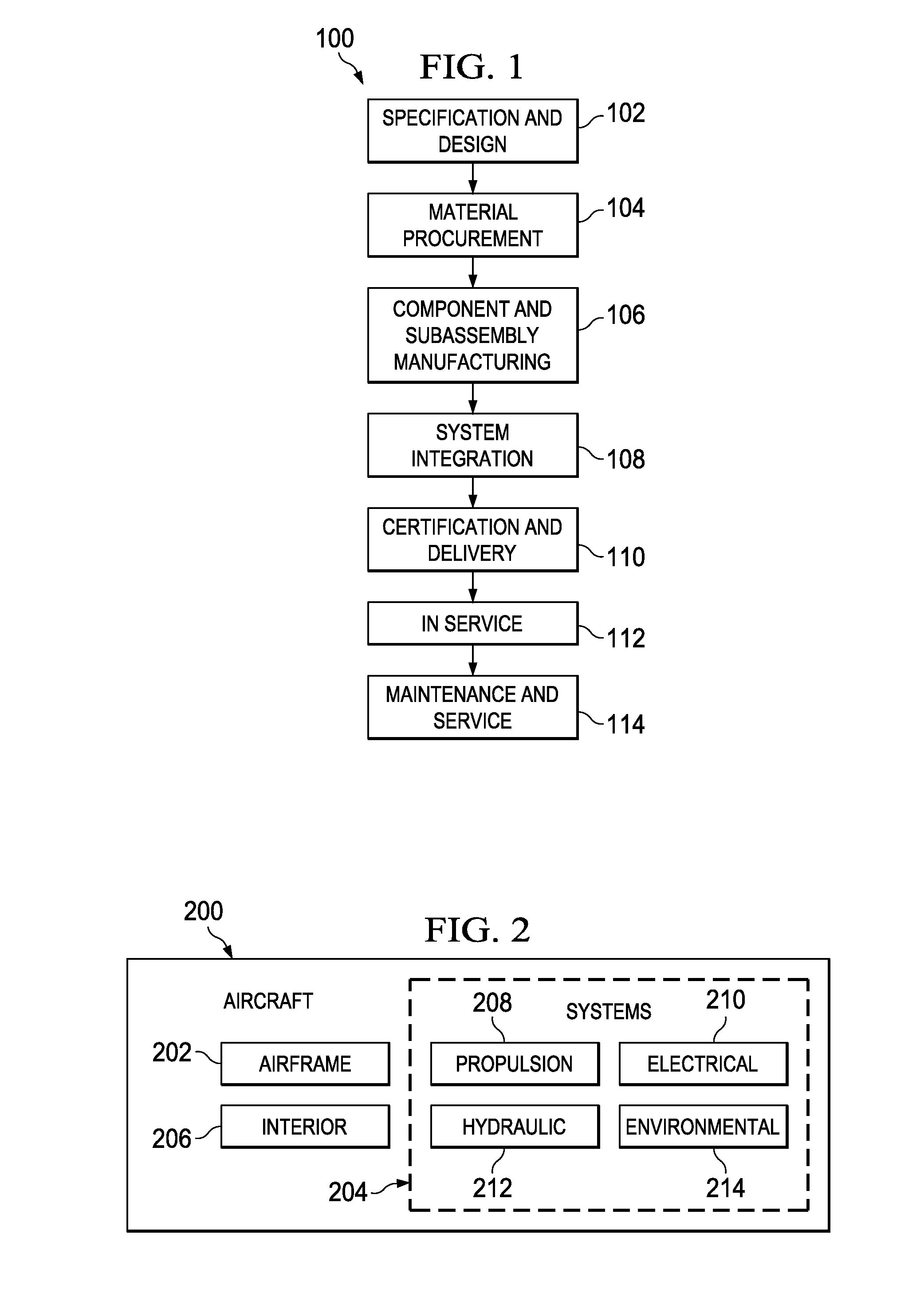
[0036]Referring more particularly to the drawings, embodiments of the disclosure may be described in the context of the aircraft manufacturing and service method 100 as shown in FIG. 1 and aircraft 200 as shown in FIG. 2. Turning first to FIG. 1, a diagram illustrating an aircraft manufacturing and service method is depicted in accordance with an advantageous embodiment. During pre-production, exemplary aircraft manufacturing and service method 100 may include specification and design 102 of aircraft 200 in FIG. 2 and material procurement 104. During production, component and subassembly manufacturing 106 and system integration 108 of aircraft 200 in FIG. 2 takes place. Thereafter, aircraft 200 in FIG. 2 may go through certification and delivery 110 in order to be placed in service 112. While in service by a customer, aircraft 200 in FIG. 2 is scheduled for routine maintenance and service 114, which may include modification, reconfiguration, refurbishment, and other maintenance or s...


PUM


Abstract

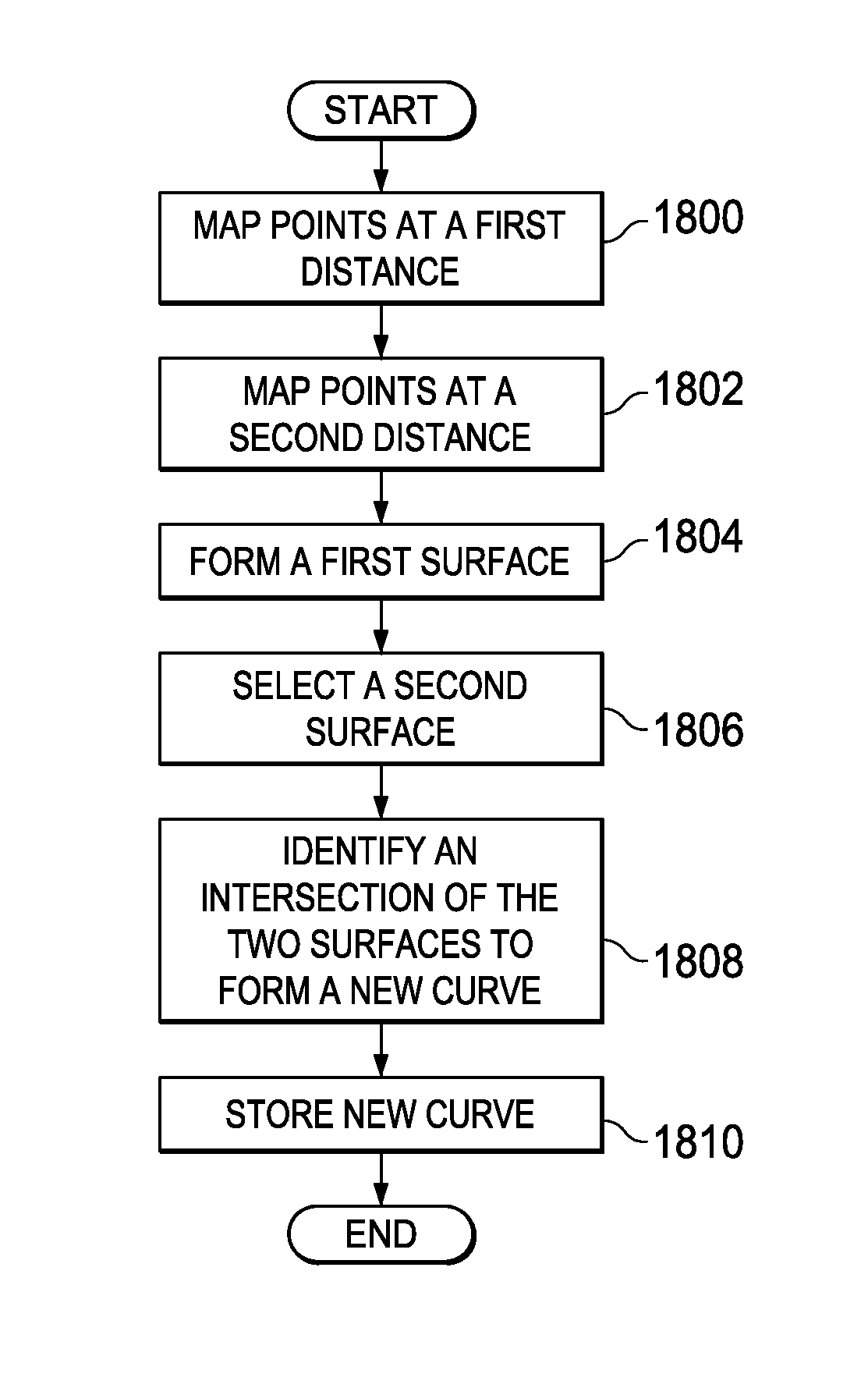
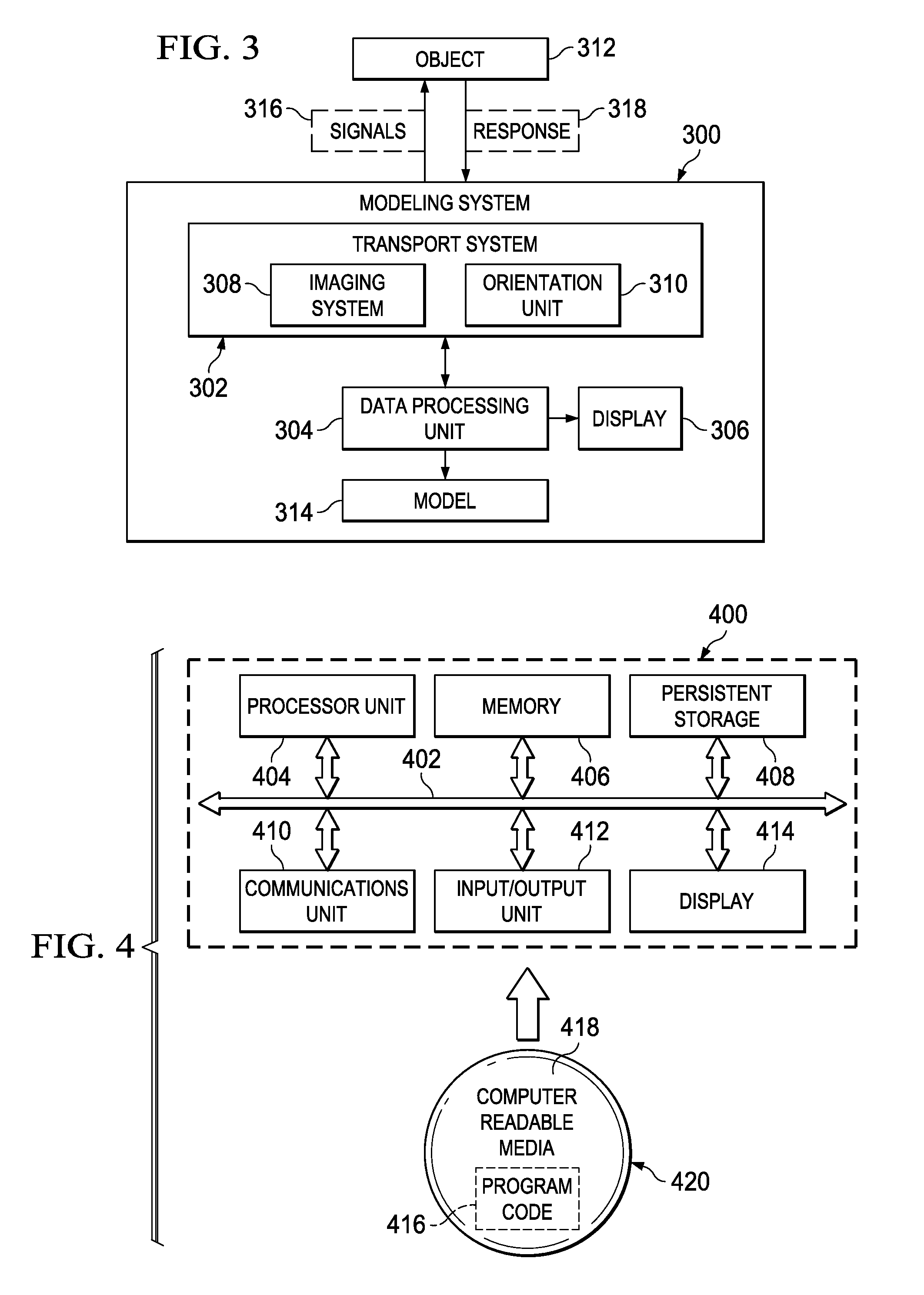
A computer implemented method, apparatus, and computer usable program code for generating a three-dimensional model of an object of interest in an aircraft. In response to transmitting a plurality of x-rays from a set of transmission points into the aircraft, backscatter x-ray data is received. The object identified from a two-dimensional diagram of the backscatter data. Points for the object are created from the identification of the object in the received data. The points are placed at a first distance from the transmission points to form a first curve. The points are placed at a second distance from the transmission points to form a second curve. A first surface is formed from the first and second curves. A second surface is formed that intersects the first surface to form an intersection. Three-dimensional data is generated for the three-dimensional model of the object from the intersection.

Description

BACKGROUND INFORMATION[0001]1. Field[0002]The present disclosure relates generally to an improved data processing system and in particular to a method and apparatus for generating data for three-dimensional models. Still more particularly, the present invention relates to a method, apparatus, and computer usable program code for generating data for three-dimensional models from x-ray data.[0003]2. Background[0004]Imaging and scanning systems have been used in a variety of manufacturing and engineering uses, including reverse engineering. For example, in reverse engineering, an object or structure, such as a vehicle, building, or complex system, may be imaged. A vehicle may include, for example, an aircraft, an automobile, a ship, a submarine, or a spacecraft. A building or complex system may include, an office building or a power plant. These images may be processed to provide two-dimensional drawings or three-dimensional models to replace and / or supplement drawings or models that m...

Claims


Application Information

Patent Timeline
Patent Type & Authority Patents(United States)
IPC IPC(8): G06T17/00G01S5/16
CPCG06T17/00G01S5/166G06T2200/08
Inventor FINLAYSON, JOHN WILLIAMSKAGGS, KIRK DOUGLASEDWARDS, WILLIAM TALIONSIEBENALER, DAVID M.GAJ, DOUGLAS DAVIDSUHR, TIMOTHY JOHNTHOMAS, JUSTINTUNG, BILLY PUNLAPCROSSON-ELTURAN, KAVA SIRVANBLUHM, THOMAS HARLANDSAFAI, MORTEZA
Owner THE BOEING CO
Learn More