Systems and methods for performing backscatter three dimensional imaging from one side of a structure

a three-dimensional imaging and composite structure technology, applied in the direction of material analysis using wave/particle radiation, instruments, diaphragm/collimeter handling, etc., can solve the problems of inability to obtain wrinkles, and known ultrasound systems that do not provide information about the thickness of features within a composite structure, etc., to achieve the effect of improving the accuracy of computed tomography, avoiding the use of large aircraft parts such as wings or fuselages

Active Publication Date: 2018-06-05
THE BOEING CO
View PDF24 Cites 3 Cited by
  • Summary
  • Abstract
  • Description
  • Claims
  • Application Information

AI Technical Summary

Problems solved by technology

Known ultrasound systems do not provide information about the thickness of features, such as wrinkles, within a composite structure because they cannot “see” past the feature from one side.
Various methods to collect three dimensional information have been attempted, but they have been impractical or slow with relatively poor accuracy, because of single X-ray insertion and collection angles.
Accordingly, computed tomography cannot be used for inspecting large aircraft parts, such as a wing or fuselage.

Method used


Image

  • Systems and methods for performing backscatter three dimensional imaging from one side of a structure
  • Systems and methods for performing backscatter three dimensional imaging from one side of a structure
  • Systems and methods for performing backscatter three dimensional imaging from one side of a structure

Examples


Embodiment Construction

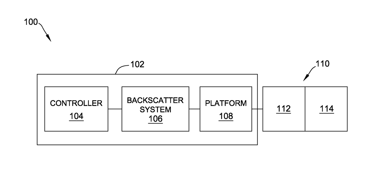
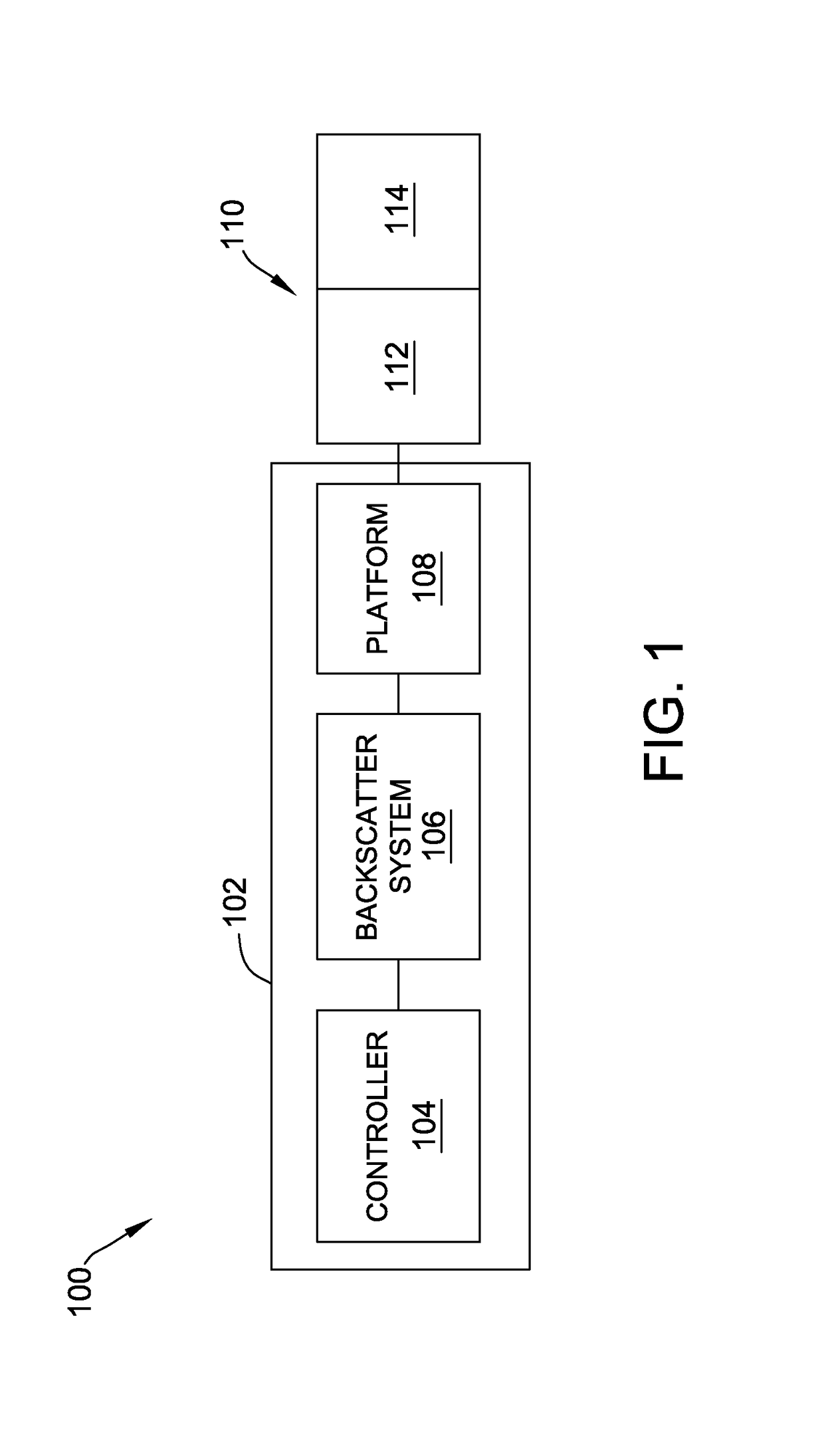
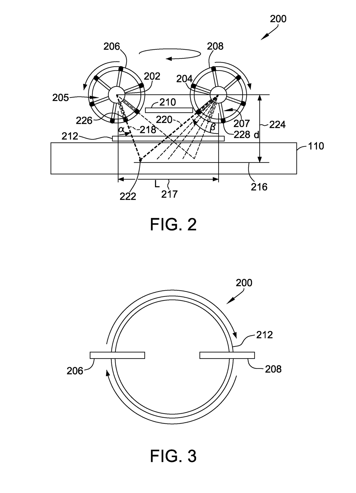
[0021]Described herein are implementations of a rotating collimator X-ray backscatter system for creating 3-D images (single and dual) through a laminography-type reconstruction. The disclosed system is portable, and scanning can be performed using a robotic arm, a stages system vacuum-mounted to a structure, a rotating stage mounted on the structure, or a crawling robot. Scanning is performed in a plane perpendicular to the structure, with each scatter point in space receiving a rotating pencil beam from two angles. These crossing beams can be made from two aligned rotating collimators (using shuttered or alternating beams), or a single rotating collimator that is precisely re-oriented (180 degrees) to scan a beam from the other side of the centerline, but in the same scan plane.

[0022]Combining of backscatter images from the two angles facilitates maximizing the scatter information from that location, and facilitates minimizing the scatter information from the surrounding area, sim...


PUM

PropertyMeasurementUnit
depthsaaaaaaaaaa
anglesaaaaaaaaaa
depthaaaaaaaaaa

Abstract

An imaging system for generating three dimensional image data using X-ray backscattering from one side of a structure is provided. The imaging system includes at least one X-ray source, at least one rotating collimator coupled to the at least one X-ray source, an X-ray detector, and a controller coupled to the at least one X-ray source, the at least one rotating collimator and the X-ray detector. The controller is configured to emit X-rays from the at least one X-ray source through the at least one rotating collimator towards the one side of the structure. Additionally, the controller is configured to detect backscattered X-rays from the one side of the structure, using the X-ray detector, at a plurality of depths within the structure. Additionally, the controller is configured to generate three dimensional image data of the structure based on the detected backscattered X-rays.

Description

BACKGROUND[0001]The present disclosure relates generally to X-ray backscatter imaging systems, and more particularly to generating three dimensional image data of features within a composite structure.[0002]Known ultrasound systems do not provide information about the thickness of features, such as wrinkles, within a composite structure because they cannot “see” past the feature from one side. There is a need to supplement ultrasonic detection of wrinkles with a method that can quantify wrinkle thickness and better determine the shape of the wrinkles. Addressing this need would provide more accurate structural performance models and predictions. X-ray laminography provides sequential layers of information for the interior of a structure. However, existing X-ray laminography systems require access to both sides of a structure, in order to operate. X-ray backscatter systems provide a tool for seeing into structures from one side only. However, images collected for inspection or evalua...

Claims


Application Information

Patent Timeline
Patent Type & Authority Patents(United States)
IPC IPC(8): G01N23/20G21K1/04G21K1/02G01N23/203
CPCG01N23/203G01N23/20025G21K1/043G01N2223/301G01N2223/1016G01N23/20008G01N2223/053G01N2223/40A61B6/022A61B6/483A61B6/5235
Inventor GEORGESON, GARY E.SAFAI, MORTEZA
Owner THE BOEING CO
Why Eureka
Try Eureka