Tilt-based look around effect image enhancement method

a look-around effect and image enhancement technology, applied in the field of image processing, can solve the problems of many types of three-dimensional systems being more expensive than existing two-dimensional imaging systems

Inactive Publication Date: 2015-04-14
LEGEND FILMS INC
View PDF367 Cites 2 Cited by
  • Summary
  • Abstract
  • Description
  • Claims
  • Application Information

AI Technical Summary

Benefits of technology

[0010]In one or more embodiments, the obtaining of the orientation of the display with respect to the reference frame includes obtaining an orientation vector from the orientation element. Some electronic devices include an orientation element that for example may provide a three-dimensional vector which indicates the direction relative to the display plane, e.g., normal to the plane in which the displays is situated. In this scenario, embodiments of the invention may determine the reference plane from which movement is related to, so as to calculate the amount of tilt about the horizontal axis, the tilt about the vertical axis, or the X and Y axes respectively. Alternatively, or in combination, embodiments of the invention may also be configured such that the obtaining of the orientation of the display with respect to the reference frame includes obtaining at least one acceleration value or angular value or both from the orientation element. This for example may be the case if the electronic device having the display includes an accelerometer or gyroscope, which are commonly provided in MEMS or Micro-Electro-Mechanical Systems packaging. Some types of electronic devices may utilize an accelerometer to provide an orientation vector as part of an Application Programming Interface. In at least one embodiment, the obtaining of the orientation of the display with respect to the reference frame includes obtaining the orientation with respect to a vector associated with gravity. In this scenario, the initial frame of reference from which to apply the look around effect is the vertical display orientation, or an angular offset thereof for example. In other embodiments, the user may assert an input that is obtained by the electronic device to signify the desired initial frame of reference. This enables the obtaining of the orientation of the display with respect to the reference frame to include obtaining the orientation with respect to an initial reference frame of the display at a particular point in time. One or more embodiments may include modifying the frame of reference over time, for example with a time averaged or time weighted function applied to orientation vector samples. This allows for a new orientation that has been applied to the display to be the starting point for further look around effect movements. This may also be utilized to apply a momentum type effect to the movement so that the image continues to move for a defined amount of time after an orientation change.
[0011]One or more embodiments may include normalizing a depth map having depth values for the at least two different pixels of the image to create the parallax map. The parallax map associated with an image for example may be encoded for the amount of pixel movement to apply to a 90 degree or full tilt for example of the display in the X or Y axes or both for example. Although a depth map, for example +10 to −5 may be utilized and calculations may be undertaken to determine a viewpoint and amount of pixel movement, the parallax map encodes on a pixel-by-pixel basis the amount of movement to minimize the processing required on the electronic device. This also lowers processing power requirements and battery requirements as well.
[0012]In addition, embodiments of the invention may also include altering values of the parallax map to exaggerate depth values. This may be performed in multiple manners, or for example using a strategy pattern to apply different exaggeration amounts based on the type of the display, e.g., two-dimensional which enjoys advantages for look around effect with higher exaggerations, or stereoscopic which in general provides enough three-dimensional effect by an of itself to warrant more limited movement nearer objects, e.g., less movement of foreground pixels. For example, one or more embodiments may include altering values of the parallax map to provide to a two-dimensional display to exaggerate depth values, for example based on a squared or cubed or higher power for example to accentuate the effect. One or more embodiments may include altering values of the parallax map to provide to a stereoscopic display to exaggerate depth values, for example as a linear or smaller relative power compared to the two-dimensional exaggerated values since the stereoscopic effect provides an easier to view look around effect for some viewers. Any other functions may be utilized to display images on different display types, and the functions may be dynamically switched when the display type is switched from two-dimensional to three-dimensional viewing or visa versa for example.
[0014]Embodiments may include obtaining a percentage of full tilt based on the orientation vector with respect to the reference frame and multiplying the percentage of full tilt by the parallax map to obtain a pixel-by-pixel amount of movement to utilize in moving the at least one pixel in the image. The multiply function may be linear or non-linear in that any function or ramp of any shape may also be utilized in the multiply operation to may slight movements more or less visible to a viewer of the display. One or more embodiments may include obtaining a percentage of full tilt based on the orientation vector with respect to the reference frame over time and multiplying the percentage of full tilt by the parallax map to obtain a pixel-by-pixel amount of movement to utilize in moving the at least one pixel in the image over time. This enables the tilt vector to have a momentum like effect of continuing to move in a smoother manner for example between two orientations.

Problems solved by technology

Many types of three-dimensional systems are more expensive than existing two-dimensional imaging systems.

Method used


Image

  • Tilt-based look around effect image enhancement method
  • Tilt-based look around effect image enhancement method
  • Tilt-based look around effect image enhancement method

Examples


Embodiment Construction

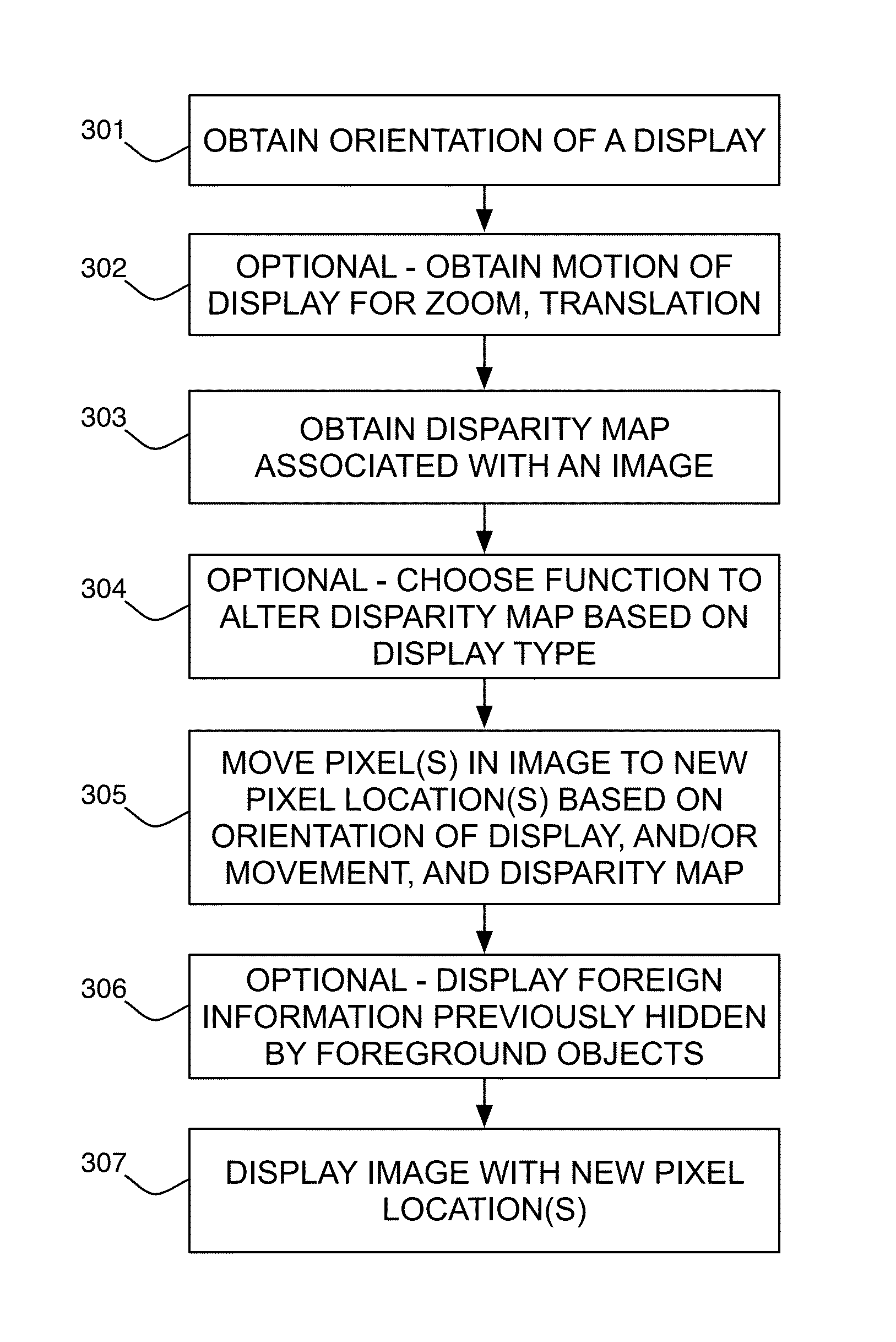
[0027]A tilt-based look around effect image enhancement method will now be described. In the following exemplary description numerous specific details are set forth in order to provide a more thorough understanding of embodiments of the invention. It will be apparent, however, to an artisan of ordinary skill that the present invention may be practiced without incorporating all aspects of the specific details described herein. In other instances, specific features, quantities, or measurements well known to those of ordinary skill in the art have not been described in detail so as not to obscure the invention. Readers should note that although examples of the invention are set forth herein, the claims, and the full scope of any equivalents, are what define the metes and bounds of the invention.

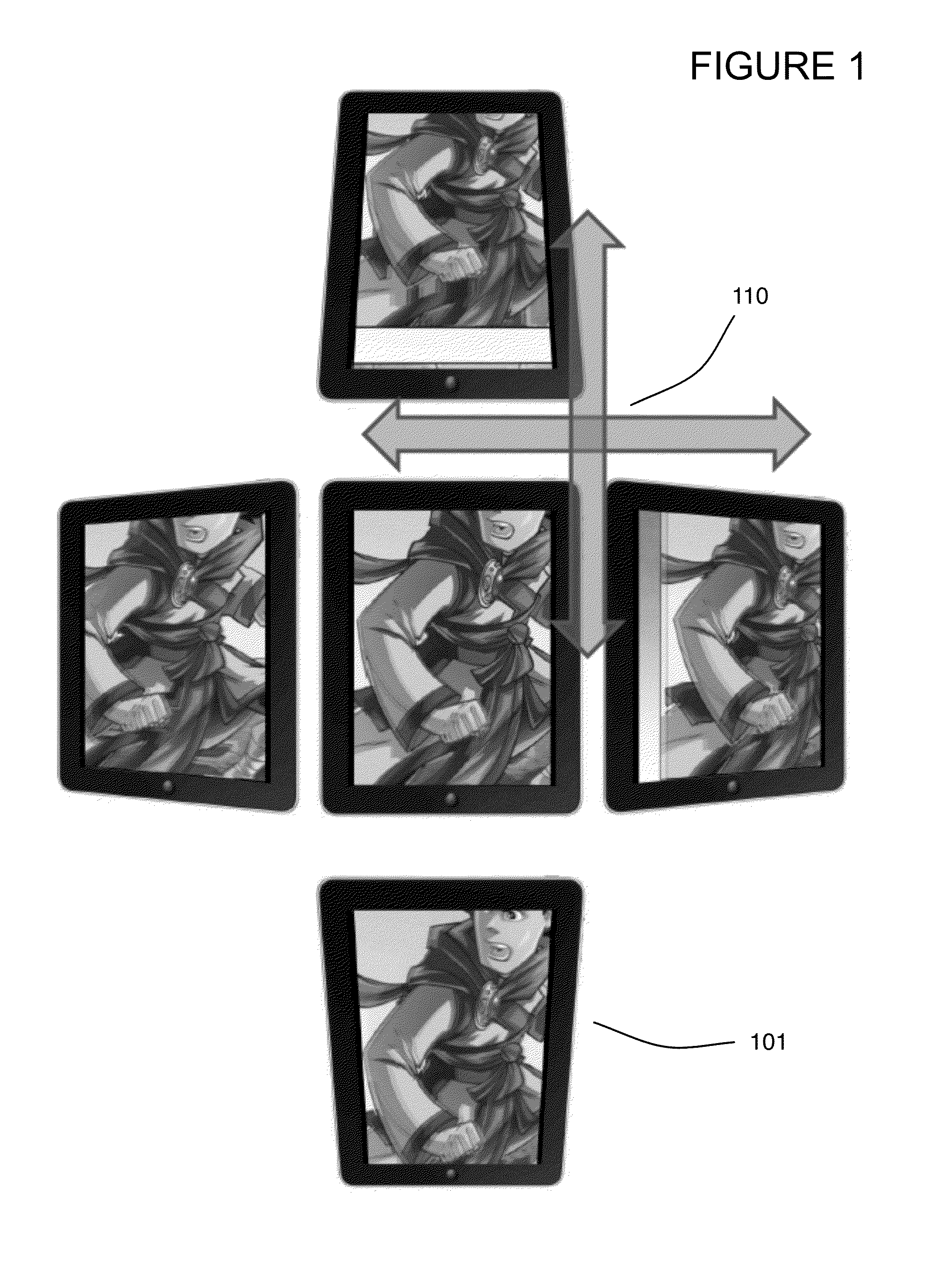
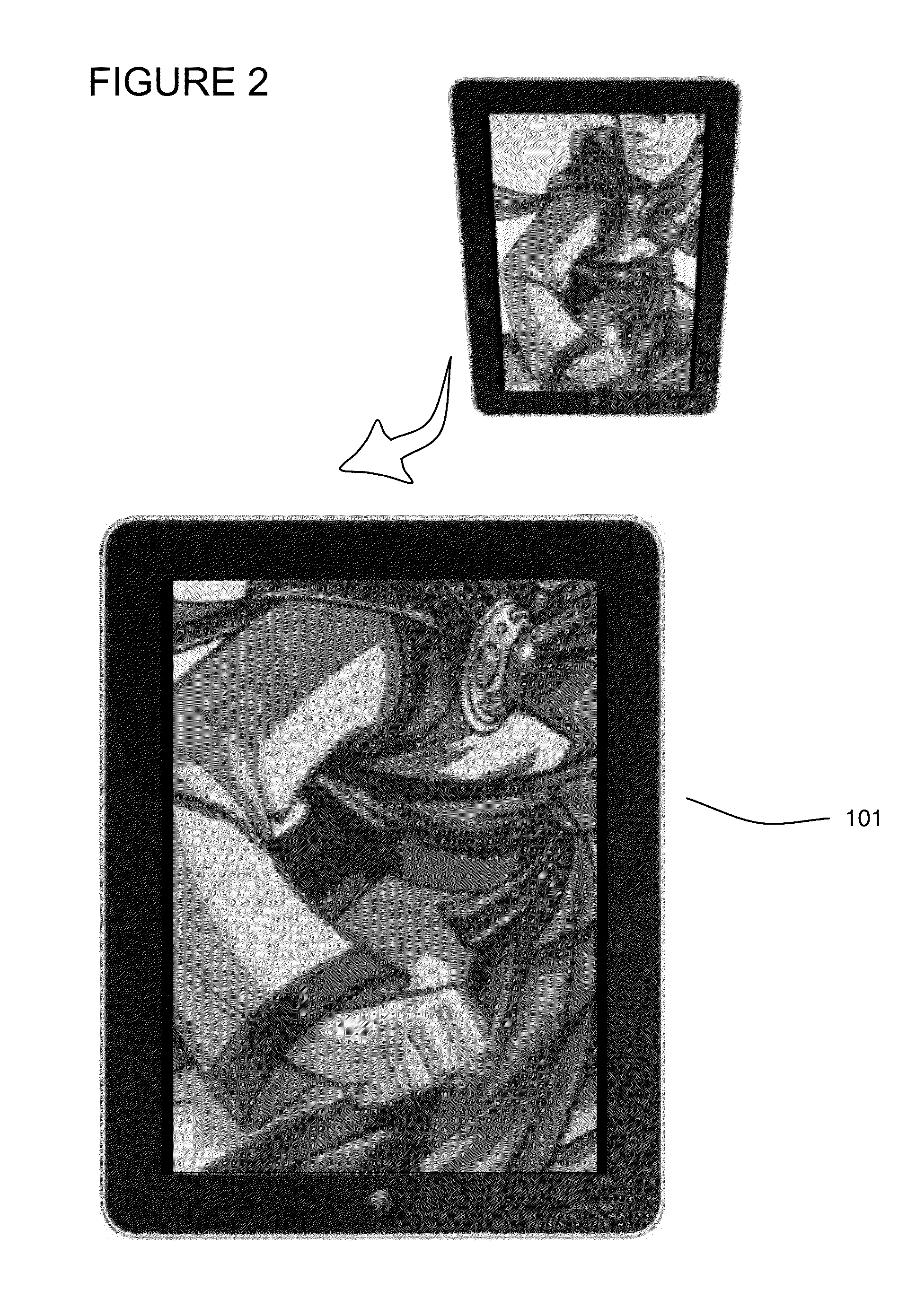
[0028]FIG. 1 illustrates an example of an electronic device configured to display a look around effect based on the tilt or orientation of the display, wherein the image is encoded as an anaglyp...


PUM


Abstract

A tilt-based look around effect image enhancement method that enables two-dimensional images to be depth enhanced and displayed for example from a different point of view based on the tilt or orientation, and / or movement of the viewing device itself. Embodiments may further alter or otherwise utilize different parallax maps to apply depth to the image based on the display type, e.g., two-dimensional or stereoscopic display, and may dynamically utilize both algorithms on a display capable of both types of display. In addition, embodiments may display information foreign to the image when portions of the image are exposed during the look around effect, including advertisements, game information, hyperlinks or any other data not originally in the image.

Description

BACKGROUND OF THE INVENTION[0001]1. Field of the Invention[0002]One or more embodiments of the invention are related to the image processing. More particularly, but not by way of limitation, one or more embodiments of the invention enable a tilt-based look around effect image enhancement method that enables two-dimensional images to be depth enhanced and displayed for example from a different point of view based on the tilt or orientation, and / or movement of the viewing device itself. Embodiments may further alter or otherwise utilize different parallax maps to apply depth to the image based on the display type, e.g., two-dimensional or stereoscopic display. In addition, embodiments may display information foreign to the image when portions of the image are exposed during the look around effect, including advertisements, game information, hyperlinks or any other data not originally in the image.[0003]2. Description of the Related Art[0004]Depth capable image displays present differe...

Claims


Application Information

Patent Timeline
Patent Type & Authority Patents(United States)
IPC IPC(8): G09G5/00G09G3/20G06T15/00G06F3/01H04N13/00H04N13/02
CPCH04N13/0278G06F3/01H04N13/0022H04N13/279H04N13/128
Inventor DEJOHN, MATTSANDREW, JAREDSCHAD, THOMASJONES, SCOTT
Owner LEGEND FILMS INC
Why Eureka
Try Eureka