
Light guide device

a technology of light guide and light source, which is applied in the direction of lighting and heating apparatus, instruments, manufacturing tools, etc., can solve the problems of low angular uniformity of devices, interfering reflections on modern computer screens, etc., and achieves the effect of improving the spatial luminance uniformity of output light, and spacing between elements

Active Publication Date: 2015-04-21
DESIGN LED PRODS
View PDF20 Cites 6 Cited by
  • Summary
  • Abstract
  • Description
  • Claims
  • Application Information

AI Technical Summary

Benefits of technology

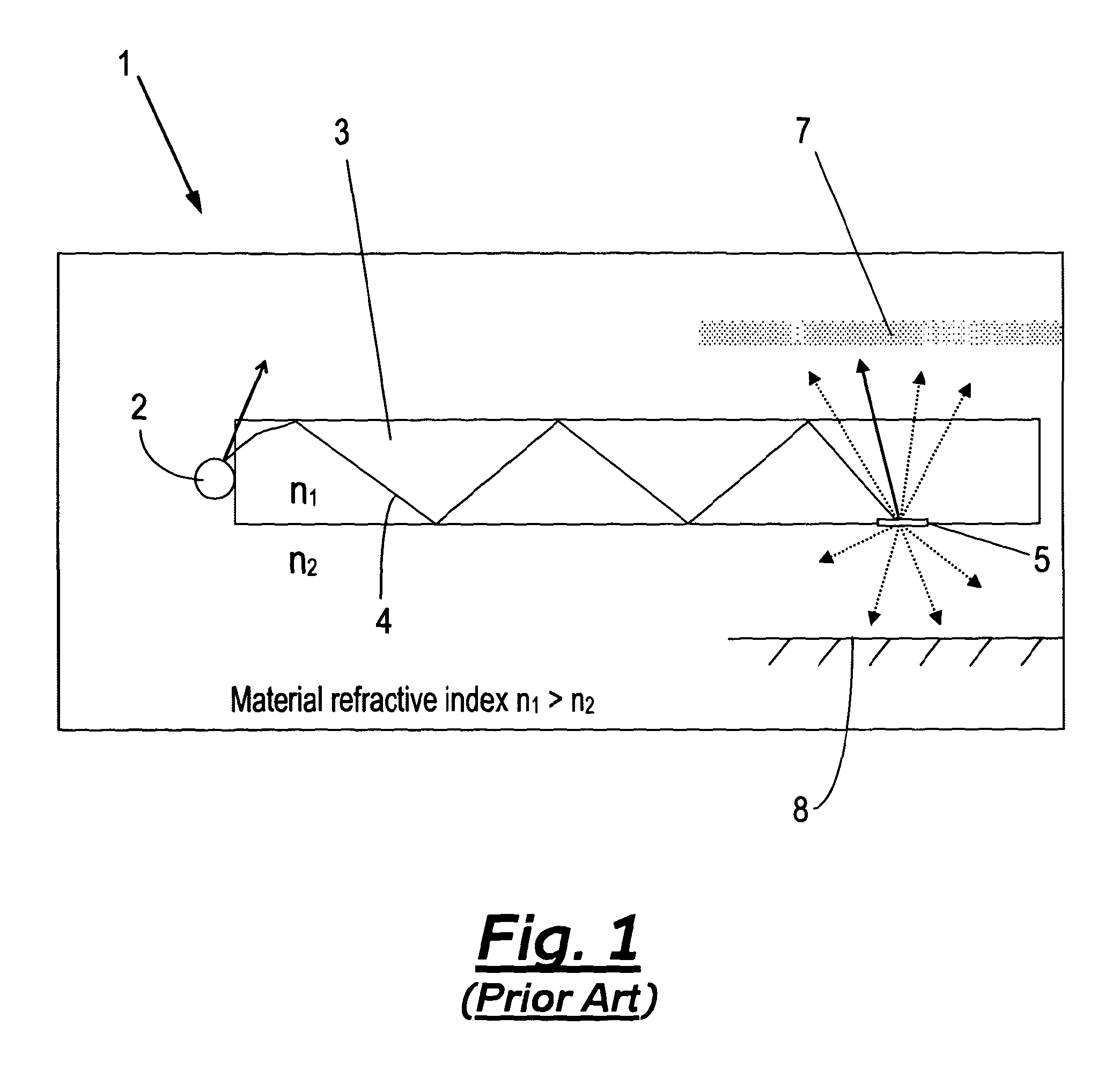
[0007]A common trait of all of the above described extraction features 5 is that they exhibit a low angular luminance uniformity which translates onto the light output from the devices 1. In order to provide an observer 6 with the appearance of uniform angular luminance it is known in the art to locate a diffuser 7 between the planar light guide 3 and the observer 6. A reflector 8, located on the opposite side of the planar light guide 3 to the observer 6, is also often employed to increase the light levels reaching the observer 6. Although the incorporation of the diffuser 7 and the reflector 8 can improve the angular uniformity of the output from a planar device e.g. to greater than 90%, the incorporation of the diffuser 7 and the reflector 8 not only add to the cost of the manufacture of the device 1 but also adds to its overall thickness.
[0032]The step of locating the interleaved pattern may provide the output light with a uniform angular luminance profile.

Problems solved by technology

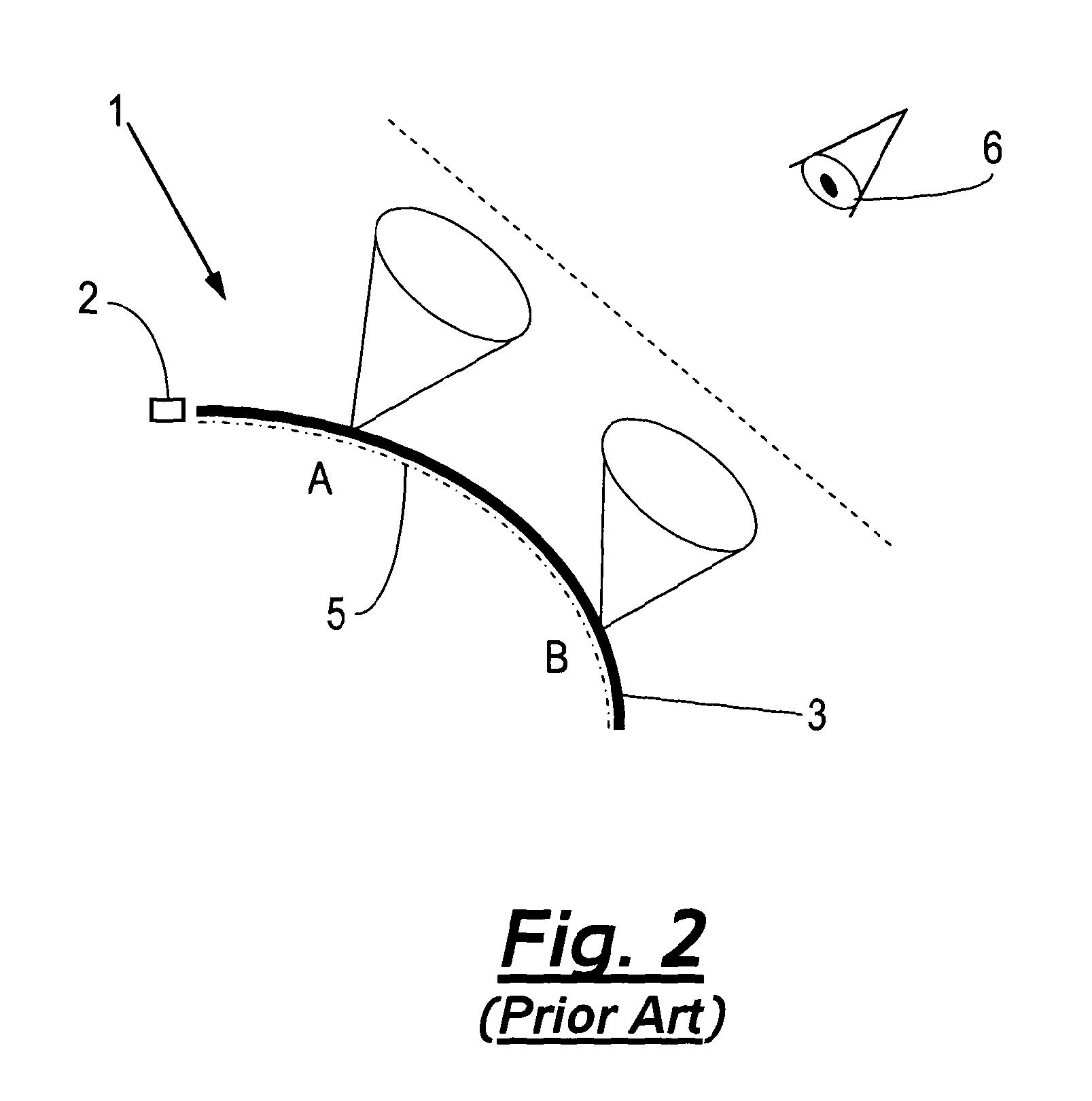
Such devices however have a light output that exhibits low angular uniformity particularly when the panel is curved or bent.
There are various reasons for the existence of these standards, for example, lighting can cause interfering reflections on modern computer screens.

Method used


Image

  • Light guide device
  • Light guide device
  • Light guide device

Examples


Embodiment Construction

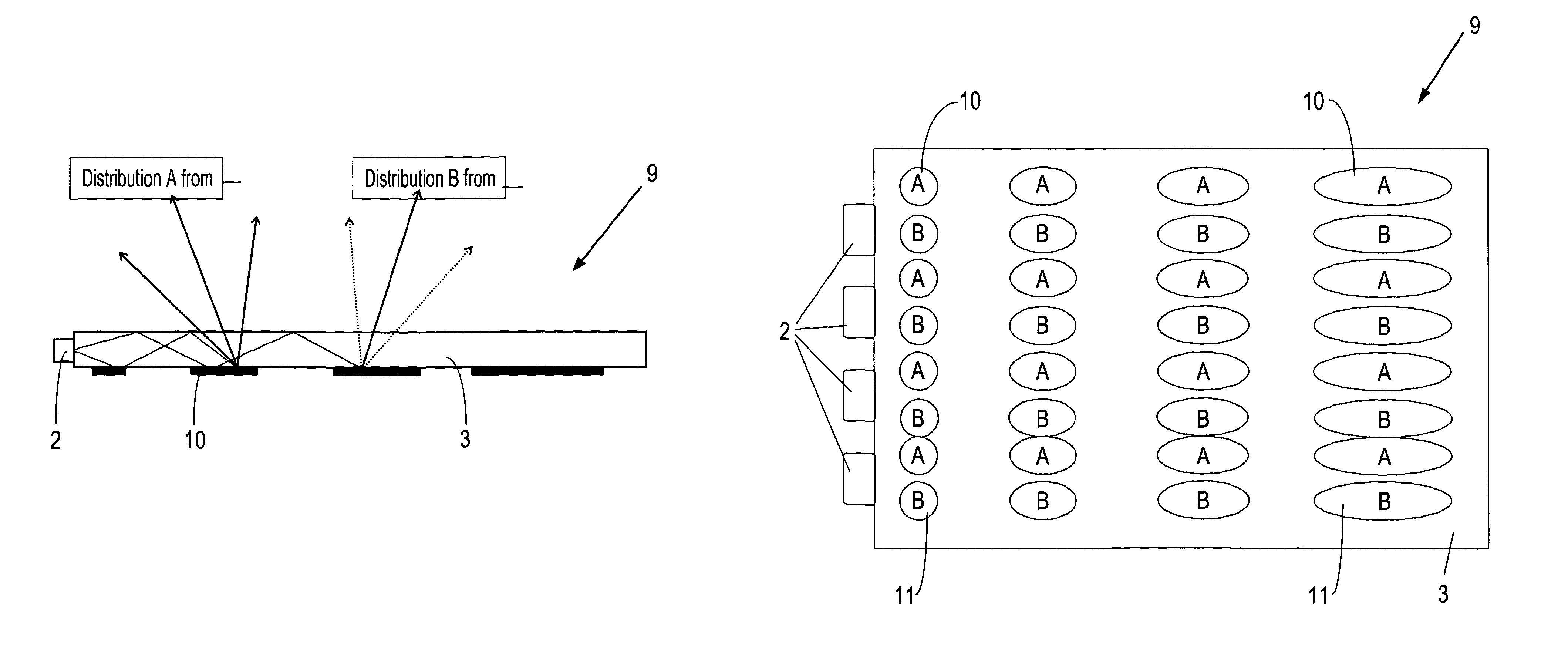
[0060]Referring to FIG. 3, a side view and bottom view of a light guide device 9 in accordance with an aspect of the present invention is presented. The light guide device 9 can be seen to comprise an array of light sources 2, in the form of LEDs, that is edge coupled to a planar light guide 3. Located across an outer surface of the planar light guide 3 are a plurality of first and second light extraction features 10 and 11. The first 10 and second light extraction features 11 are deployed across the surface of the planar light-guide 3 within an interleaved pattern.

[0061]FIG. 3(b) provides further detail of the interleaved pattern between the first 10 and second light extraction features 11. As can be seen the interleaved pattern comprises alternative rows of first 10 and second light extraction features 11. The surface area of the extraction features 10 and 11 can be seen to increases the further the extraction features are from the light source 2.

[0062]In the embodiment presented ...


PUM

PropertyMeasurementUnit
anglesaaaaaaaaaa
thicknessaaaaaaaaaa
thicknessaaaaaaaaaa

Abstract

A light guide device for illumination, lighting and display purposes that exhibits an output light having a predetermined, and preferably uniform, angular luminance profile is described. The device comprises a light guide (13) suitable for guiding light coupled thereto and a plurality of extraction features (10, 11) located on one or more surfaces of the light guide. The plurality of extraction features comprises an interleaved pattern of first (11) and second extraction features the arrangement of which provides a means for defining the predetermined angular and spatial luminance profiles for the output light. The device allows for a uniform angular luminance profile to be produced that is maintained even when the light guide is curved or bent.

Description

[0001]This application is the U.S. national phase of International Application No. PCT / GB2011 / 050980 filed 24 May 2011 which designated the U.S. and claims priority to GB Patent Application No. 1008599.1 filed 24 May 2010, the entire contents of each of which are hereby incorporated by reference.[0002]The present invention relates to a light guide device for illumination, lighting and display purposes and, particularly, to a light guide device that exhibits an output light having a predetermined, and preferably uniform, angular luminance profile.[0003]A number of light-guide devices are known to those skilled in the art. These devices are employed for a range of functions including illumination, backlighting, signage and display purposes. For example, it is known in the art to employ fibre optic lighting technology to produce flat, bendable lighting panels for LCD backlighting. In such devices a plastic or glass optical fibre employed to guide the light is woven into a flat, bendabl...

Claims


Application Information

Patent Timeline
Patent Type & Authority Patents(United States)
IPC IPC(8): F21V7/04F21V8/00F21V17/04
CPCG02B6/0033G02B6/0036G02B6/0061F21V17/04G02B6/0055Y10T29/49Y10T29/49826G02B6/0058G02B6/0066
Inventor GOURLAY, JAMES
Owner DESIGN LED PRODS
Learn More