
Improved angular uniformity waveguide for augmented or virtual reality

a technology of augmented or virtual reality and waveguide, applied in the field of waveguide, can solve the problems of reducing the angular uniformity of colours across the field of view of the waveguide, and achieve the effect of improving the angular uniformity of colours, uniform display, and improving the performance of the waveguid

Pending Publication Date: 2022-06-02
SNAP INC
View PDF0 Cites 0 Cited by
  • Summary
  • Abstract
  • Description
  • Claims
  • Application Information

AI Technical Summary

Benefits of technology

The invention relates to an improved waveguide that can provide better angular uniformity of colors and reduce the effects of non-uniform lighting. This can be achieved by arranging multiple optical structures on the waveguide surface. These optical structures can have a rectangular or grid shape and can be surface relief structures or coated to further control diffraction efficiency. The arrangement of the optical structures also improves the waveguide's performance by increasing the proportion of light that is turned and coupled towards the user. Overall, this invention provides a more uniform display and better viewing experience for the user.

Problems solved by technology

One issue that has been identified with known waveguides because a central strip in the output image has been observed as having a higher relative brightness than other parts.
Despite being able to reduce the central “striping effect” these waveguides still suffer from the issue of reduced angular uniformity of colours across the field of view.

Method used


Image

  • Improved angular uniformity waveguide for augmented or virtual reality
  • Improved angular uniformity waveguide for augmented or virtual reality
  • Improved angular uniformity waveguide for augmented or virtual reality

Examples


Embodiment Construction

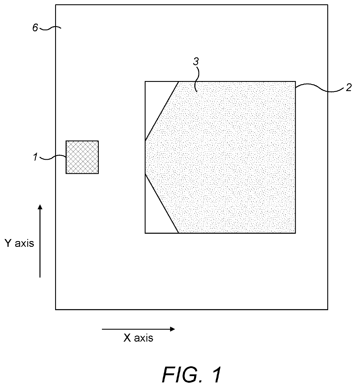
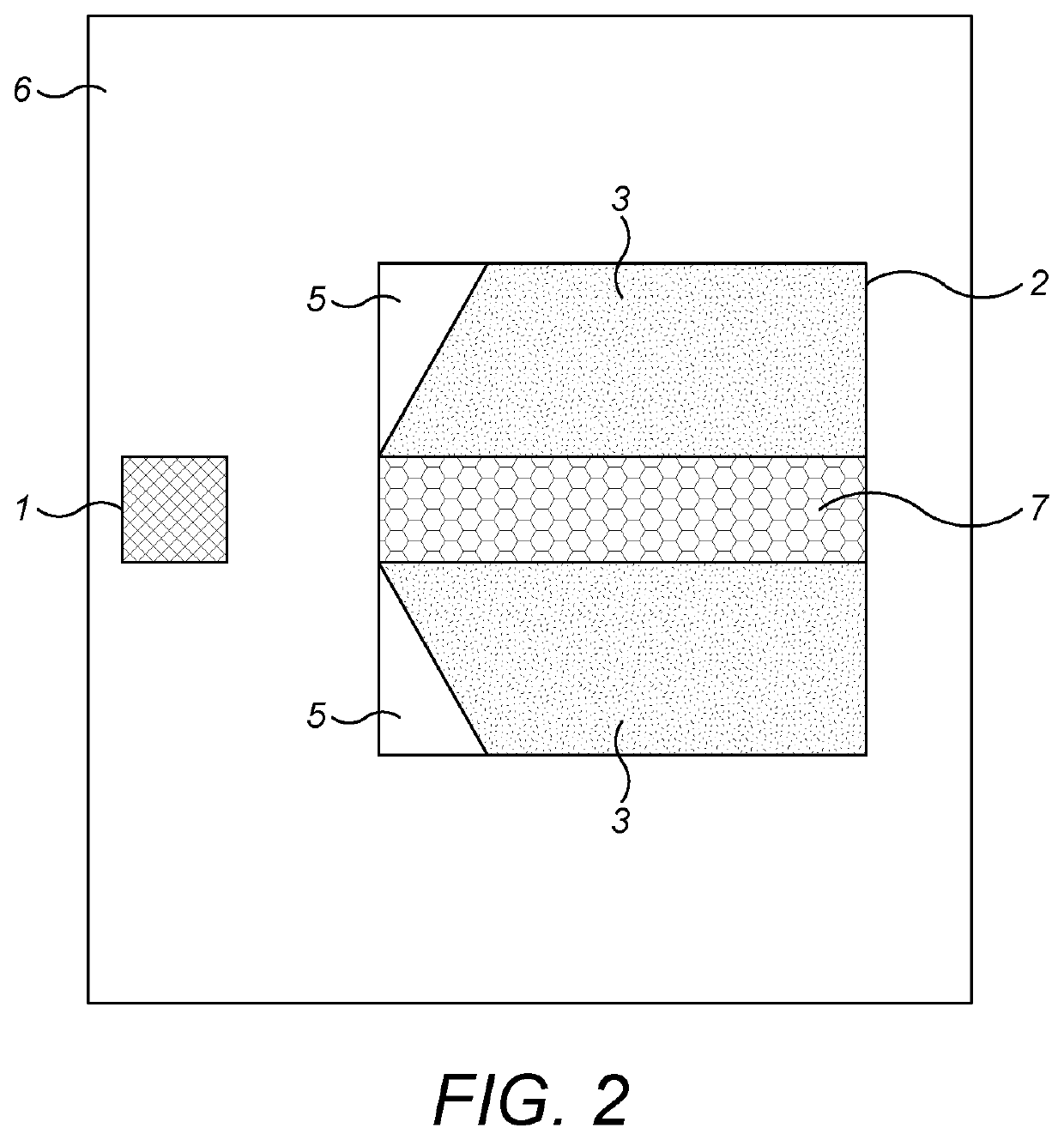
[0042]FIGS. 1 and 2 are top views of a known waveguide 6. An input diffraction grating 1 is provided on a surface of the waveguide 6 for coupling light from a projector (not shown) into the waveguide 6. Light that is coupled into the waveguide travels by total internal reflection towards an output element 2 which includes a photonic crystal 3. In this example the photonic crystal 3 includes pillars (not shown) having a circular cross-sectional shape from the perspective of these top views. The pillars have a different refractive index relative to the refractive index of the surrounding waveguide medium and they are arranged in an array having hexagonal symmetry.

[0043]When light encounters the photonic crystal 3 in the output element 2 from the input diffraction grating along the x-axis it is either transmitted or turned through ±60° by one of the diffractive optical structures formed by the array in the photonic crystal 3.

[0044]It has been found that the output image diffracted from...


PUM


Abstract

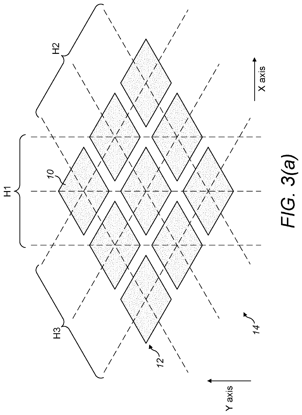
There is disclosed a waveguide for use in an augmented reality or virtual reality display. The waveguide comprises a plurality of optical structures in a photonic crystal. The plurality of optical structures are arranged in an array to provide at least two diffractive optical elements. Each of the two diffractive optical elements is configured to receive light from an input direction and couple it towards the other diffractive optical element which can then act as an output diffractive optical element, providing outcoupled orders towards a viewer. The plurality of optical structures respectively have a shape, when viewed in the plane of the waveguide, comprising twelve substantially straight sides, six of the sides having respective normal vectors at a first angle, and the other six of the sides having respective normal vectors at a second angle which is different to the first angle.

Description

TECHNICAL FIELD[0001]The present invention relates to a waveguide for use in an augmented reality or virtual reality display. In particular, the invention relates to a waveguide in which input light is expanded in two orthogonal directions in an output element and is coupled out of a waveguide towards a viewer. This can allow physical expansion of the eyebox in an augmented reality display.BACKGROUND[0002]An augmented reality display allows a user to view their surroundings as well as projected images. In military or transportation applications the projected images can be overlaid on the real world perceived by the user. Other applications for these displays include video games and wearable devices, such as glasses.[0003]In a normal augmented reality set-up a transparent display screen is provided in front of a user so that they can continue to see the physical world. The display screen is typically a glass waveguide, and a projector is provided to one side. Light from the projector...

Claims


Application Information

Patent Timeline
Patent Type & Authority Applications(United States)
IPC IPC(8): G02B27/01G02B27/42
CPCG02B27/0172G02B27/4272G02B27/4205G02B27/0081G02B2027/0174
Inventor ALEXEEV, ARSENYDE CUNSEL, SEBASTIENFOX, SOPHIAGAN, CHOON HOWPHELAN, CIARANSIROKI, GLEBVALERA, MOHMED SALIMWANG, KAI
Owner SNAP INC
Learn More