
Electro-optical dimming system

a technology of optical dimming and optical dimming, which is applied in the field of projection display dimming, can solve the problems of significant effects on the viewability of the display, inability to provide the precise dimming control needed for many critical applications, and inability to easily read information from the display in high ambient light conditions, etc., to achieve the effect of improving reliability, facilitating precise dimming range, and dissipating the associated hea

Inactive Publication Date: 2005-11-08
HONEYWELL INT INC
View PDF6 Cites 3 Cited by
  • Summary
  • Abstract
  • Description
  • Claims
  • Application Information

AI Technical Summary

Benefits of technology

The system enables precise control of light output across a wide dimming range, enhancing image quality and reliability while minimizing heat-related issues, effectively addressing the limitations of prior art solutions.

Problems solved by technology

Without a sufficiently high maximum dimming ratio, a viewer of the display may be unable to easily read information from the display in high ambient light conditions, low ambient light conditions, or both.
This is typically of greatest concern in low light conditions, where small changes in the amount of dimming can have significant effects on the viewability of the display.
Unfortunately, many prior dimming solutions have been unable to provide the precise dimming control needed for many critical applications.
Unfortunately, prior art solutions to dimming in projection displays have met with limited success.
As mentioned above, some prior art solutions have been unable to reliably achieve the wide dimming range or the precise dimming control needed for certain critical applications.
Other prior art solutions have required excessively complex structures that require large amounts of space and suffered from high cost and low reliability.
Some prior art solutions have also negatively impacted the high bright state luminance required for bright ambient conditions.
Other prior art solutions have been highly susceptible to malfunction caused by heat absorption.

Method used


Image

  • Electro-optical dimming system
  • Electro-optical dimming system
  • Electro-optical dimming system

Examples


first embodiment

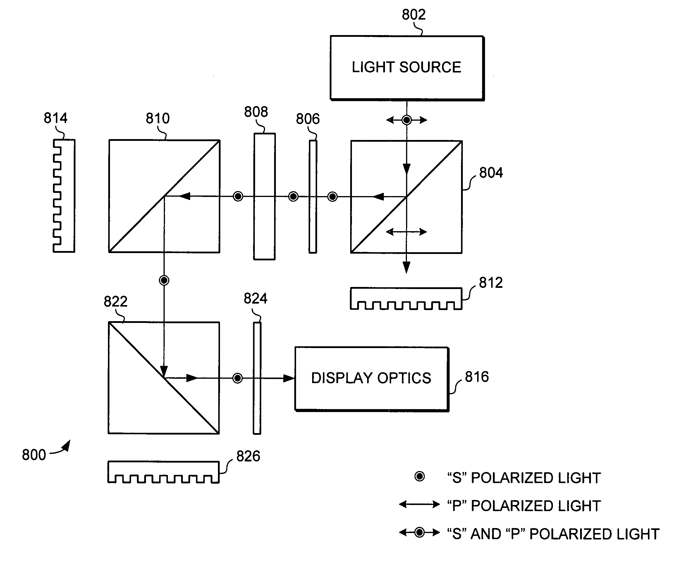
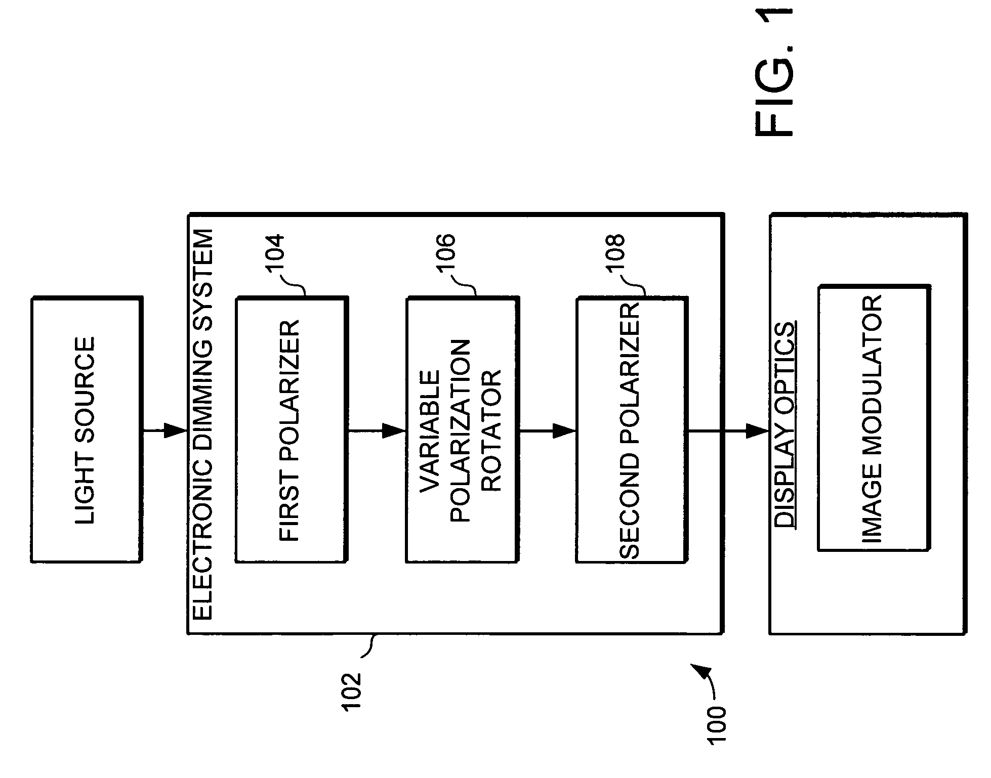
[0021]In a first embodiment, the first polarizer and the second polarizer comprise non-absorbing polarizers and the dimming system further includes a heat absorber. In this specification, a non-absorbing polarizer is defined as a polarizer that does not use absorption as its primary means of polarization. One type of non-absorbing polarizer is a reflective polarizer such as a polarizing beam splitter. Polarizing beam splitters are polarizers that separate the different polarizations of light spatially. Another type non-absorbing polarizer is a scattering polarizer. Another type non-absorbing polarizer is a birefringent refractive polarizer. Another example of non-absorbing polarizers are polarization converters that convert light to desired polarization. A polarization converter may include one or more of the other types of polarizers. Likewise, an absorbing polarizer is one that uses absorption as its primary means of polarization. Examples of absorbing polarizers include typical d...

third embodiment

[0024]In a third embodiment, the variable polarization rotator comprises a pair of variable polarization rotators selected and configured to have substantially opposite angular variation. Like the other embodiments, this embodiment provides the ability to control the amount of light passed to the display by selectively rotating the polarization of the light with the pair of variable polarization rotator. However, in this embodiment a pair of rotators are used that have substantially opposite angular variation. By using such a pair of rotators, angular variation caused by one rotator can be substantially cancelled by the angular variation in the other rotator. The image quality is improved by providing improved angular uniformity in the light output of the dimmer. Thus, this embodiment is able to precisely control the amount of light passed to the display while providing a light source with improved angular uniformity.

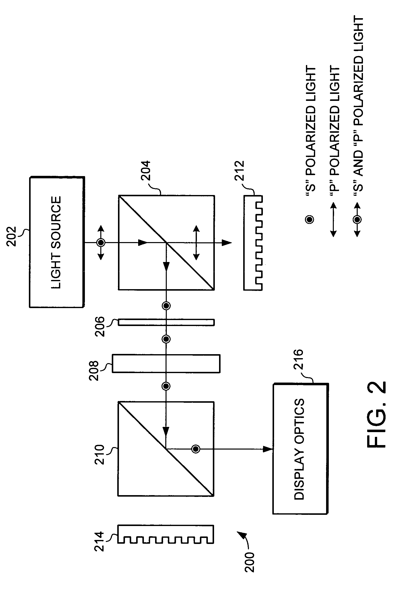
[0025]Turning now to FIGS. 2 and 3, a first exemplary embodiment o...


PUM


Abstract

An electronic dimming system for use in projection displays is provided. In a first embodiment, the dimming system comprises a first non-absorbing polarizer, a variable polarization rotator, a second non-absorbing polarizer and a heat absorber. The first non-absorbing polarizer receives light from a light source and passes the light of a selected polarization to the variable polarization rotator. The variable polarization rotator selectively rotates the polarization of the received light. The light passes from the variable polarization rotator to the second non-absorbing polarizer. The second non-absorbing polarizer passes only light of a second selected polarization. The light that passes the second non-absorbing polarizer is passed to the display, where it is used to illuminate the display. The system provides the ability to control the amount of light passed to the display by selectively rotating the polarization of the light with the variable polarization rotator.

Description

FIELD OF THE INVENTION[0001]This invention generally relates to projection displays, and more specifically applies to dimming in projection displays.BACKGROUND OF THE INVENTION[0002]Various types of optical displays are commonly used in a wide variety of applications. Included among these various types of displays are projection displays. Projection displays typically involve optical relaying of the displayed image prior to viewing. A typical projection display system will often include a diffuse viewing screen. One of the attractive characteristics of many projection displays is the flexibility of configuring a system with the particular features needed for a specific application.[0003]One important performance parameter in certain projection displays is the range of luminance that can be provided by a projection display, commonly referred to as the dimming range. In many applications it is critical that a display make information clearly visible in a wide variety of ambient light ...

Claims


Application Information

Patent Timeline
Patent Type & Authority Patents(United States)
IPC IPC(8): G03B21/20G03B21/14
CPCG03B21/2053G03B21/2073
Inventor DUBIN, MATTHEW B.LARSON, BRENT D.WALKER, BRIAN W.
Owner HONEYWELL INT INC
Learn More