Mobile training device

a training device and mobile technology, applied in the field of training devices, can solve the problems of difficult setup and use in field training, device does not train or improve the user's lower body strength or rotational strength, and the structure of the device is complicated, so as to achieve the effect of convenient movement of the devi

Active Publication Date: 2015-04-21
TAMH ENTERPRISES
View PDF31 Cites 11 Cited by
  • Summary
  • Abstract
  • Description
  • Claims
  • Application Information

AI Technical Summary

Benefits of technology

[0021]In one embodiment, another engaging means at or around the guide holes is provided so that the elastic ropes can pass through the rings on the training belt and circle back to hook on the engaging means, thus providing theoretically double resistance.
[0023]In one embodiment, the base has for legs, two on the user side and two on the other side, for balance and stability purposes. However, the number and position of the legs may vary for the consideration of space, cost or weight, etc. In one embodiment, the back legs further have rollers attached for easily moving the device around.

Problems solved by technology

However, such device does not train or improve the user's lower body strength or rotational strength.
However, such device is complicated in structure, thus costly, and not easy to setup and use in a field training, such as a batting cage practice.
However, such device trainings the body only along one axis, and it is of no practical use in a field training.
However, this type of device does not work on the torso strength, especially on the rotation strength.
Little, if any, muscle strength is improved using this device.
However, insufficient resistance could be provided by the device, and a customized bat / club / racket must be provided in order to work with such device, making it impractical.
However, that device has a large footprint and complicated structure, which is not easy to set up for field practice.
Additionally, that device only provides resistance on the horizontal plane for rotation, without simultaneously addressing the issue of improving the vertical strength from the leg.
However, the position where the rope connects the belt is not fixed but instead a sliding connection, which effectively defeats the purpose of it because the sliding connection will significantly reduce the resistance from the rope.
In addition, the fact that it does not provide a base is a disadvantage because fixing the rope on any object means the length of the rope needs to be constantly adjusted, and finding a fixture around a training site to tie the rope to is not always easy.

Method used


Image

  • Mobile training device
  • Mobile training device
  • Mobile training device

Examples


Embodiment Construction

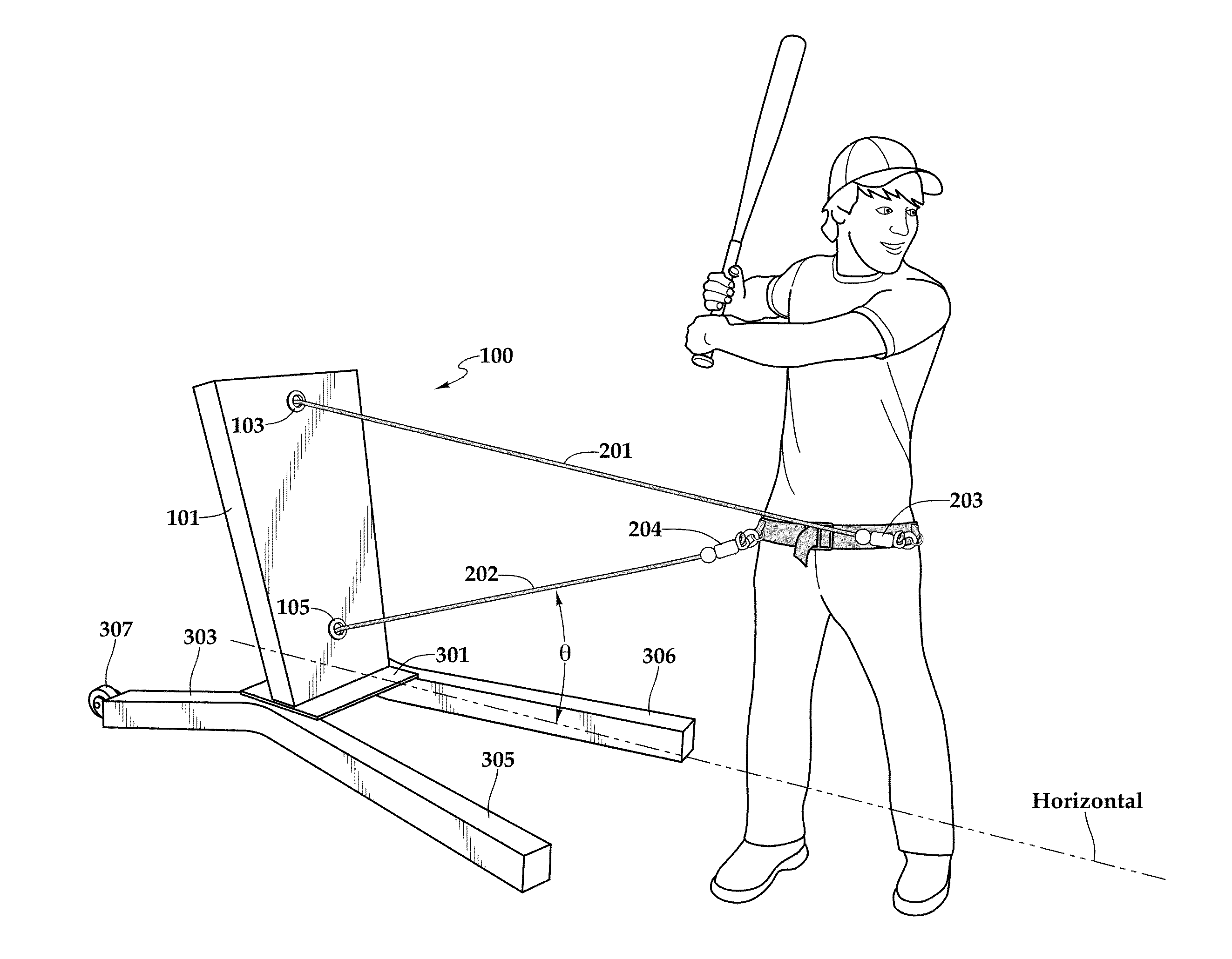
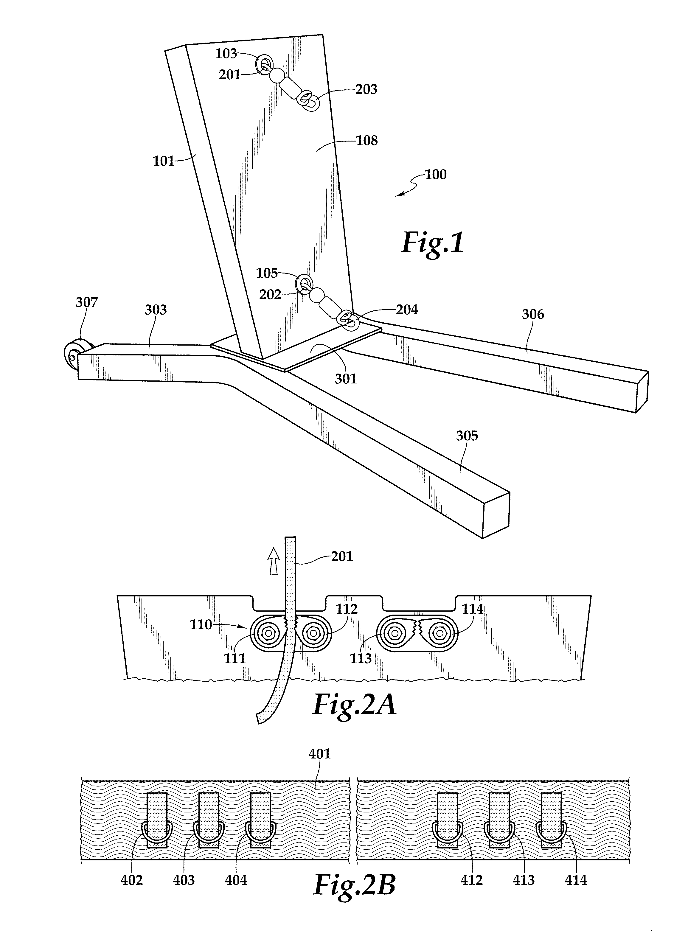
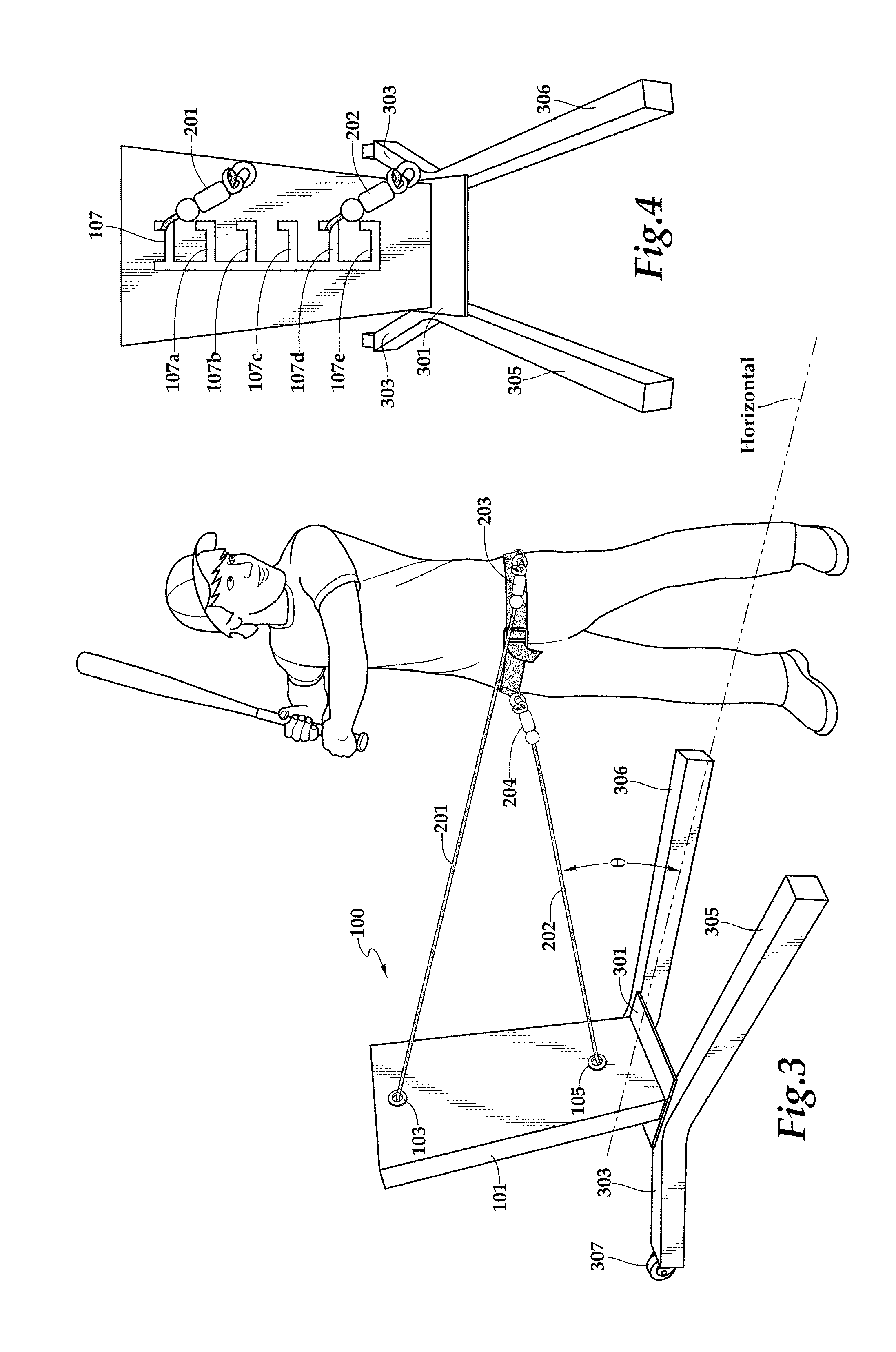
[0040]FIG. 1 illustrates the mobile training device of the present invention. As shown in the figure, the training device 100 comprises an upright frame 101, and a base 301. The upright frame 101 has a front cover 108 on which locates a first guide hole 103 and a second guide hole 105. A first elastic rope 201, preferably stored as a reel inside the frame 101, extends from the first guide hole 103, and a second elastic rope 202 extends from the second guide hope 105. The elastic ropes are secured by clamps mounted on the frame 101, as seen in FIG. 2A. Both the first and second elastic ropes 201, 202 have a hook 203, 204 attached to the end of the ropes, respectively. The hook 203 is used to engage with a ring on a training belt (discussed later in FIG. 2B). But other equivalent mechanism may be used, such as a carabiner.

[0041]The upright frame 101 is attached to a base 301. The base 301 has two back legs 303 (only showing one in this figure) and two front legs 305, 306. The term “fr...


PUM


Abstract

The present invention relates to a mobile training device having bi-directional, variable resistive forces for training a baseball swing and other sports involving weight transfer and hip rotation.

Description

PRIOR RELATED APPLICATIONS[0001]This invention claims priority to PCT / US13 / 21697 entitled “MOBILE TRAINING DEVICE” which was filed on Jan. 16, 2013. The patent application is incorporated by reference in its entirety.FEDERALLY SPONSORED RESEARCH STATEMENT[0002]Not applicable.FIELD OF THE INVENTION[0003]The invention relates to a training device. More particularly, the invention relates to an training device that can provide resistance simultaneously on two different axes with easy installation, stable during use and the ease of varying resistance.BACKGROUND OF THE INVENTION[0004]In certain sports, the transfer of body weight is considered the core of training. For example, in baseball the swing movement, the weight is first transferred to the back leg and then moved forward to generate energy. At the same time the back ankle starts rotation along with the back knee and the hip, which in turn bring the upper body, shoulder and arm to also rotate around the center of the body. In this...

Claims


Application Information

Patent Timeline
Patent Type & Authority Patents(United States)
IPC IPC(8): A63B69/00
CPCA63B69/0002A63B21/0442A63B21/0557A63B69/0059A63B2069/0008A63B2071/025A63B2071/026A63B2225/093A63B2225/12A63B21/4009A63B21/4025A63B21/4043
Inventor HALLMARK, TIMOTHY M.
Owner TAMH ENTERPRISES
Why Eureka
Try Eureka