
Measurement device for external fixation frame

a measurement device and fixation frame technology, applied in the field of measuring devices, can solve the problems of patients not wanting to visit the physician's office, patients may not adjust their external fixators according to the correction plan, and the mastery of the products themselves and the related techniques for use can be a long and daunting process,

Active Publication Date: 2015-04-28
STRYKER EURO OPERATIONS HLDG LLC
View PDF17 Cites 10 Cited by
  • Summary
  • Abstract
  • Description
  • Claims
  • Application Information

AI Technical Summary

Benefits of technology

The present invention provides an instrument for determining an angle between two parts of an external fixation device. The instrument consists of a face with a connector for attaching it to the first part of the device, a rotatable dial, and an elongate member pivotally connected to the dial. The instrument also includes a coupling for connecting it to the second part of the device. The first part of the device can also be rotated with respect to the second part. The instrument can be easily attached and used to accurately measure the angle between the two parts of the external fixation device. This can be useful in orthopedic procedures where external fixation devices are used.

Problems solved by technology

However, mastery of the products themselves and related techniques for use can be a long and daunting process that is not attractive to many users.
Patients, however, may not desire to visit the physician's office every time an adjustment is needed.
On some occasions, however, patients may not adjust their external fixator according to the correction plan for a variety of reasons.
For instance, patients may not understand how to use the external fixator correctly.
In addition, when the patients themselves adjust the external fixators, physicians may not even know whether patients are in fact adjusting the external fixators according to the correction plan.

Method used


Image

  • Measurement device for external fixation frame
  • Measurement device for external fixation frame
  • Measurement device for external fixation frame

Examples


Embodiment Construction

[0022]In describing the preferred embodiments of the subject illustrated and to be described with respect to the drawings, specific terminology will be used for the sake of clarity. However, the invention is not intended to be limited to any specific terms used herein, and it is to be understood that each specific term includes all technical equivalents, which operate in a similar manner to accomplish a similar purpose.

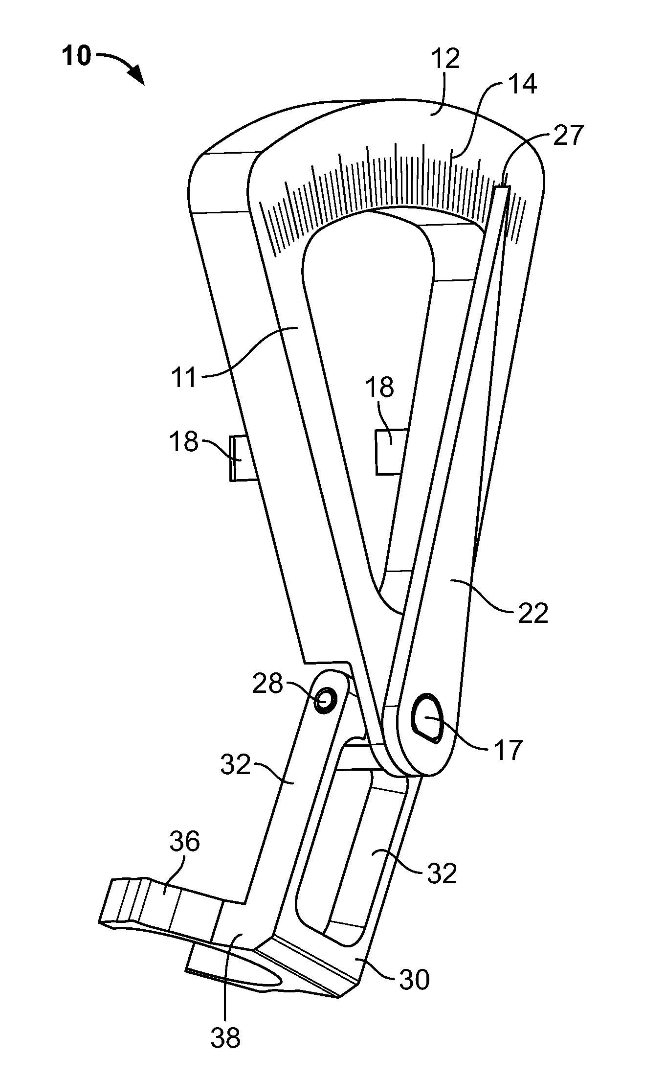
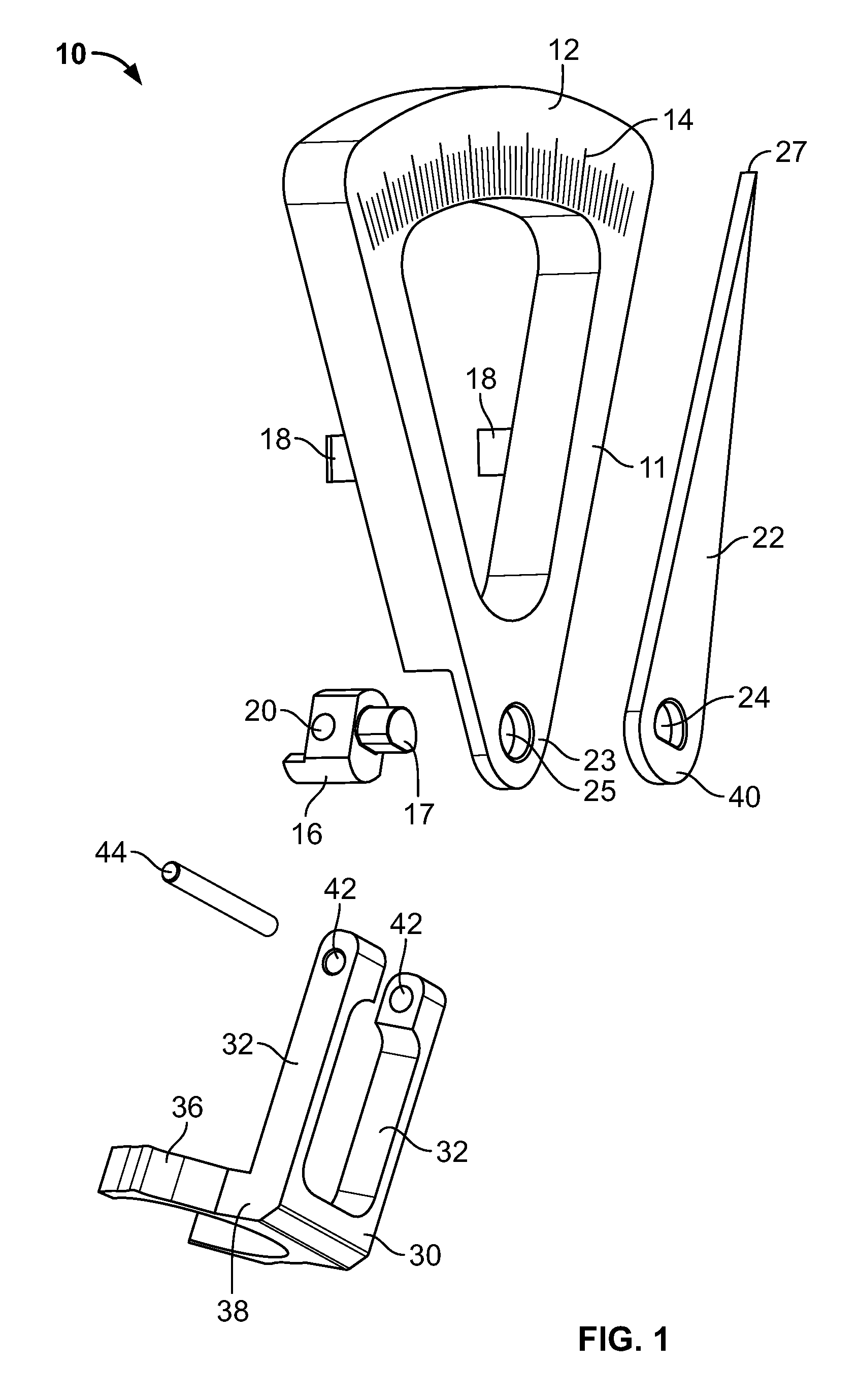
[0023]Referring to FIG. 1, a device 10 may include several elements, among which may be: (1) a protractor member 11 having a face 12 with angle designations 14 thereon; (2) a rotatable dial 22 rotatably engaged or mounted to the face 12; and (3) an elongate member 30 having arms 32 projecting therefrom and an opposing clamp 36 coupled thereto. In use, device 10 may be positioned on an external fixation frame to determine the angle between two respective portions or points on such frame, as described more fully below.

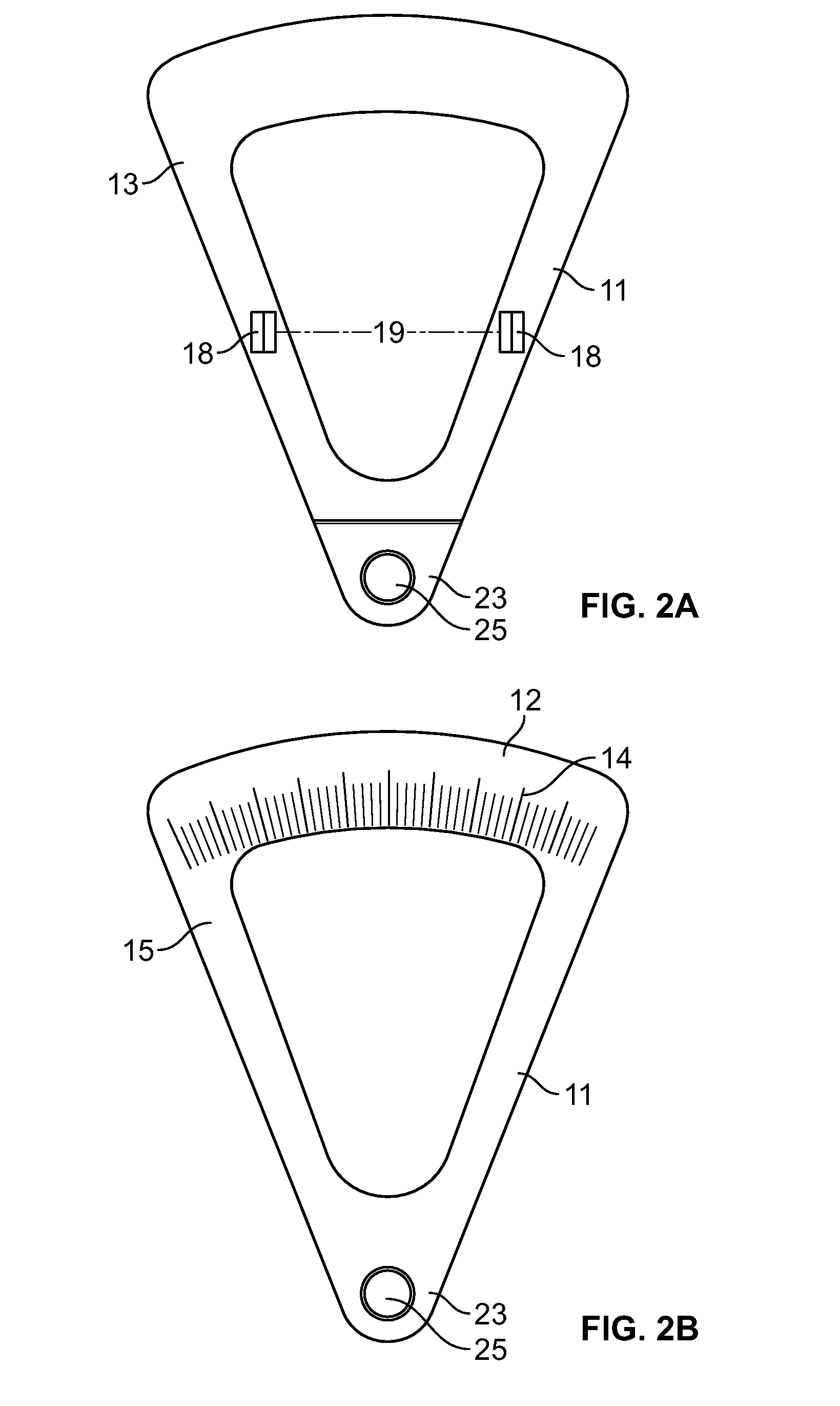
[0024]Referring to FIG. 2A, the face 12 of protracto...


PUM


Abstract

A protractor for use with an external fixation frame is provided. The protractor may include a face having angle designations thereon and a set of opposed and extending flanges projecting from said face. The flanges may connect to a portion of an external fixation frame, such as a ring (or other component) of the frame. The face may also include a post member to which a rotatable dial is mounted. An elongate member may be pivotally connected to a portion of the post member and may include a clamp. The clamp may be used to connect to an alternate portion of an external fixation frame, such as a strut of the frame. Thus, the protractor may be connected to two points on an external fixation frame so as to measure the angle between such points. Related methods of using the aforementioned protractor are also disclosed.

Description

FIELD OF THE INVENTION[0001]The present invention relates generally to measuring devices that may be used to measure the angle between respective portions of a medical device, and in particular to protractor-type devices for measuring the angle between respective portions of an external fixation frame.BACKGROUND OF THE INVENTION[0002]In the external fixation industry, it is often necessary to realign, reposition, and / or securely hold two bone elements relative to one another. For example, in the practice of medicine, bone fragments and the like must sometimes be aligned or realigned and repositioned to restore boney continuity and skeletal function. External fixators may be utilized for this purpose, e.g., such fixators may be used to treat several injuries and / or deformities, including: acute fractures of the skeleton, soft tissue injuries, delayed union of the skeleton when bones are slow to heal, nonunion of the skeleton when bones have not healed, malunion whereby broken or frac...

Claims


Application Information

Patent Timeline
Patent Type & Authority Patents(United States)
IPC IPC(8): A61B17/58A61F2/00A61B17/70
CPCA61B17/7074A61B17/62A61B2090/067A61B90/06
Inventor EDELHAUSER, ADAM JOHNHEINSOHN, JAN
Owner STRYKER EURO OPERATIONS HLDG LLC
Learn More