Locking pliers with handle locking mechanism

a technology of locking mechanism and pliers, which is applied in the field of pliers, can solve the problems of pliers springing open and disengaging from the workpi

Active Publication Date: 2015-05-12
STANLEY WORKS THE
View PDF26 Cites 12 Cited by
  • Summary
  • Abstract
  • Description
  • Claims
  • Application Information

AI Technical Summary

Benefits of technology

[0003]According to one aspect of this disclosure, a pair of pliers includes an upper structure including an upper jaw and an upper handle extending from the upper jaw, and a lower structure including a lower jaw and a lower handle, the lower jaw configured to pivot relative to the upper jaw. The lower handle is configured to pivot relative to the lower jaw. The pair of pliers additionally includes an overcenter linkage operatively connected between the upper structure and the lower structure, the linkage biasing the lower handle and the lower jaw away from the upper handle and the upper jaw, respectively, when in a jaw-opening position, and enabling the lower jaw and the lower handle to be retained in a closed configuration when the linkage is in a jaw-closing position. The pair of pliers further includes a lock member movable between a locking configuration and a release configuration. When the lock member is in the locking configuration, it prevents pivoting movement of the lower handle from the closed configuration and retains the jaws in a closed position. When the lock member is in the release configuration, it enables the lower handle to be moved away from the closed configuration and allows the jaws to move to an open position.

Problems solved by technology

It may be appreciated, however, that bumping or otherwise unintentionally disturbing such pliers in such an overcenter locked position may cause the pliers to spring open and disengage from the work piece.

Method used


Image

  • Locking pliers with handle locking mechanism
  • Locking pliers with handle locking mechanism
  • Locking pliers with handle locking mechanism

Examples


Embodiment Construction

)

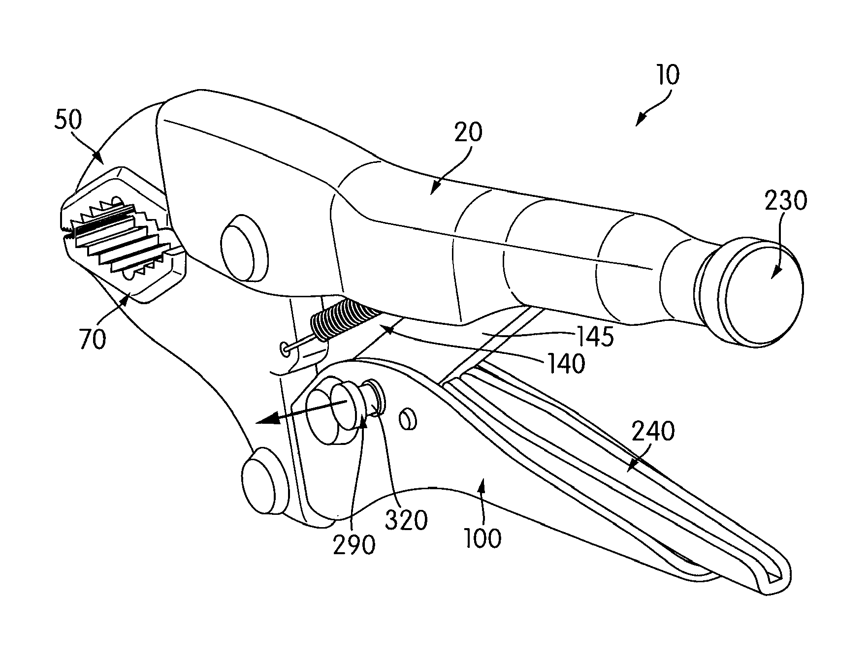
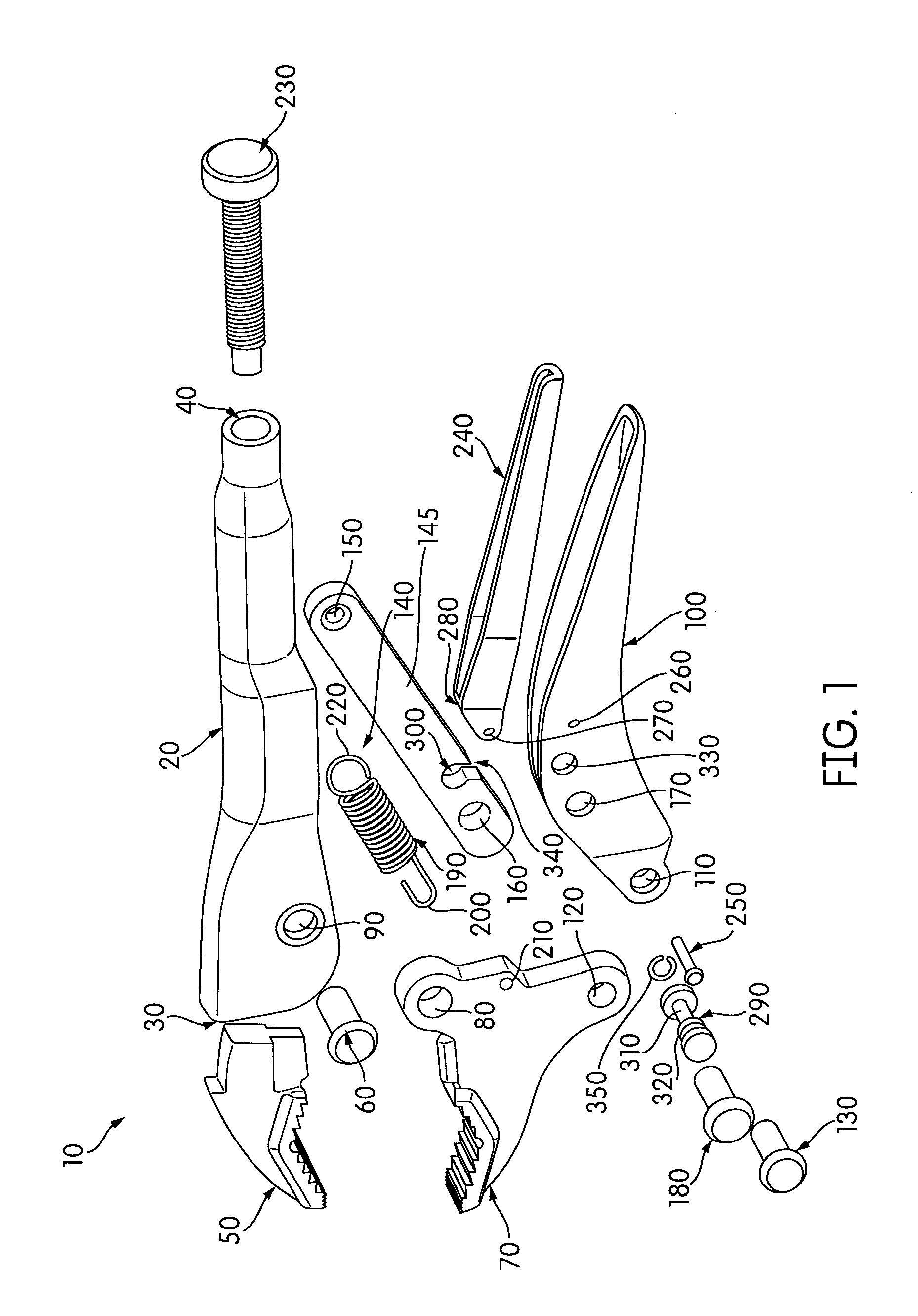
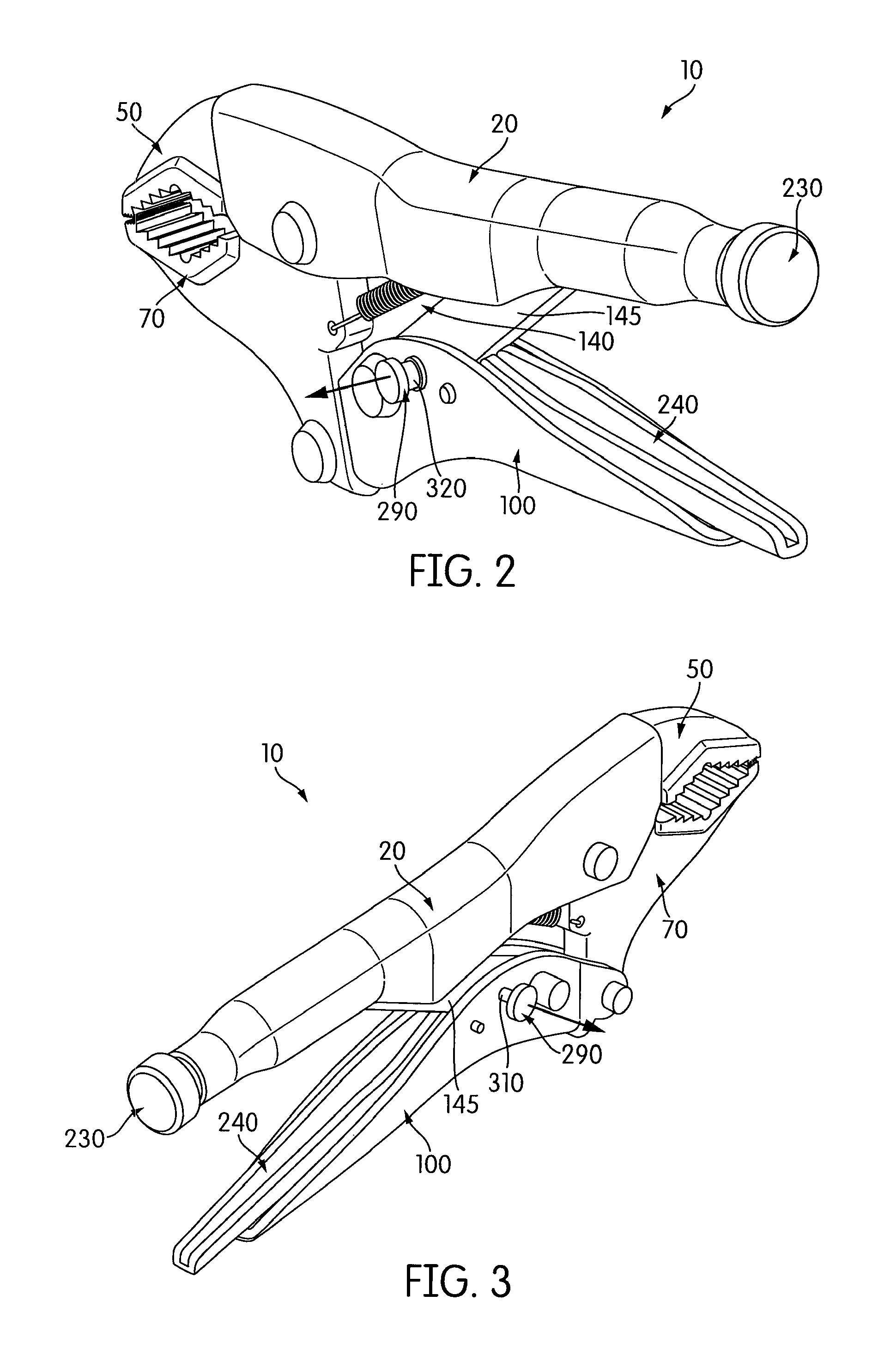
[0012]FIG. 1 illustrates an exploded view of an embodiment of a pair of locking pliers 10 of the present invention, wherein components thereof may be seen. The locking pliers 10 comprise an upper handle 20 that is elongated between a first end 30 and a second end 40. Received in the first end 30 is an upper jaw 50 of the locking pliers 10, forming an upper structure. As shown in the illustrated embodiment, the upper jaw 50 may be slidably received into the first end 30, and may be secured thereto by any appropriate manner, including but not limited to being welded, glued, removably or non-removably attached by one or more mechanical fasteners, or so on. In some embodiments, the upper jaw 50 may be integrally formed at the first end 30 of the upper handle 20.

[0013]Pivotally coupled to the handle 20 by a first pivot pin 60 is a lower jaw 70. As shown in the illustrated embodiment, a first pivot hole 80 of the lower jaw 70 is configured to be received in the upper handle 20, and align...


PUM


Abstract

Pliers include upper structure including an upper jaw and handle extending therefrom, and lower structure including a lower jaw and handle. The lower jaw may pivot relative to the upper jaw, and the lower handle may pivot relative to the lower jaw. An overcenter linkage operatively connects between the upper and lower structure, biasing the lower handle and jaw away from the upper handle and jaw, respectively, when in a jaw-opening position, and enabling the lower jaw and handle to be retained in a closed configuration when the linkage is in a jaw-closing position. A lock member is movable between a locking configuration preventing pivoting of the lower handle from the closed configuration and retaining the jaws in a closed position, and a release configuration enabling the lower handle to be moved away from the closed configuration, allowing the jaws to move to an open position.

Description

FIELD OF THE INVENTION[0001]The present invention relates generally to pliers having an overcenter locking position.BACKGROUND OF THE INVENTION[0002]Locking pliers generally rely on an “overcenter” linkage to lock the pliers into a position compressing jaws thereof against a work piece. It may be appreciated, however, that bumping or otherwise unintentionally disturbing such pliers in such an overcenter locked position may cause the pliers to spring open and disengage from the work piece. Among other things, the present application relates to preventing pliers from unintentionally moving from an overcenter locked position.SUMMARY OF THE INVENTION[0003]According to one aspect of this disclosure, a pair of pliers includes an upper structure including an upper jaw and an upper handle extending from the upper jaw, and a lower structure including a lower jaw and a lower handle, the lower jaw configured to pivot relative to the upper jaw. The lower handle is configured to pivot relative t...

Claims


Application Information

Patent Timeline
Patent Type & Authority Patents(United States)
IPC IPC(8): B25B7/14B25B7/12
CPCB25B7/123
Inventor CRIPPS, BRIAN
Owner STANLEY WORKS THE
Why Eureka
Try Eureka