Lighting fixture assembly

a technology for lighting fixtures and assemblies, applied in fixed installations, lighting and heating devices, support devices, etc., can solve the problems of lack of hardware extending from the top panel to the bottom panel, lack of hardware extending therethrough, etc., to improve the aesthetics of lighting fixture assemblies, reduce the visibility of supporting hardware, and eliminate the effect of internal supporting hardwar

Inactive Publication Date: 2015-05-12
3FORM
View PDF13 Cites 20 Cited by
  • Summary
  • Abstract
  • Description
  • Claims
  • Application Information

AI Technical Summary

Benefits of technology

[0011]Implementations of the present invention solve one or more of the foregoing or other problems in the art with lighting fixture assemblies that reduce or otherwise minimize the visibility of supporting hardware. In particular, lighting fixture assemblies of the present invention may include one or more external panels that define, in whole or in part, an internal space where light bulbs and / or other electrical components are housed. The internal space of such lighting fixture assemblies may lack hardware extending therethrough. Accordingly, one or more implementations can improve the aesthetic qualities of the lighting fixture assemblies by eliminating the visibility of internal supporting hardware and reducing or eliminating shadows cast by supporting hardware.
[0013]Another implementation of a lighting fixture assembly includes one or more side panels and a bottom panel having an outer edge comprising a plurality of protrusions. A plurality of fastening mechanisms secure the plurality of protrusions of the bottom panel to the one or more side panels. The plurality of protrusions create a gap between portions of the outer edge of the bottom panel and the one or more side panels. The gap reduces shadows between the one or more side panels and the bottom panel.

Problems solved by technology

The internal space of such lighting fixture assemblies may lack hardware extending therethrough.
Furthermore, no hardware extends from the top panel to the bottom panel.

Method used


Image

  • Lighting fixture assembly
  • Lighting fixture assembly
  • Lighting fixture assembly

Examples


Embodiment Construction

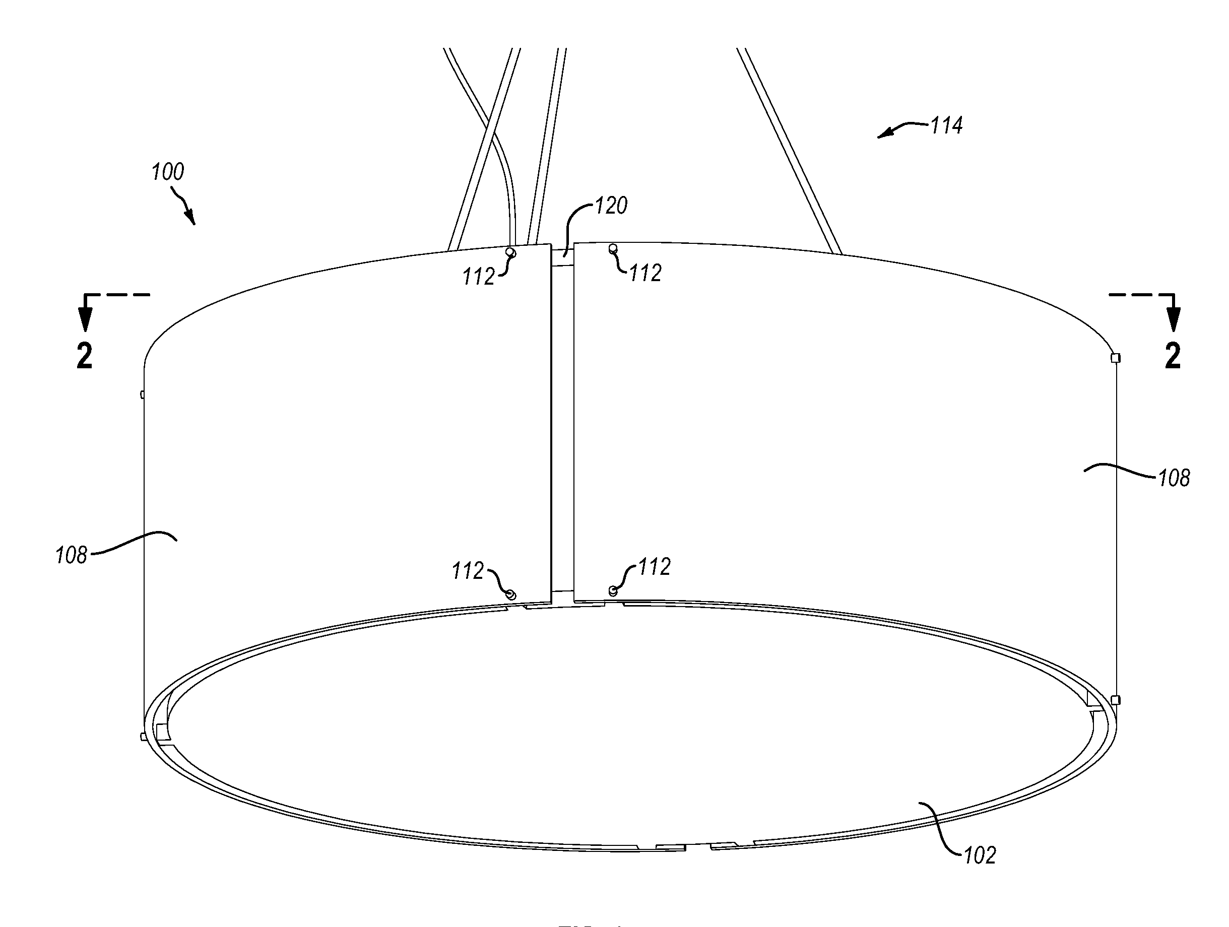
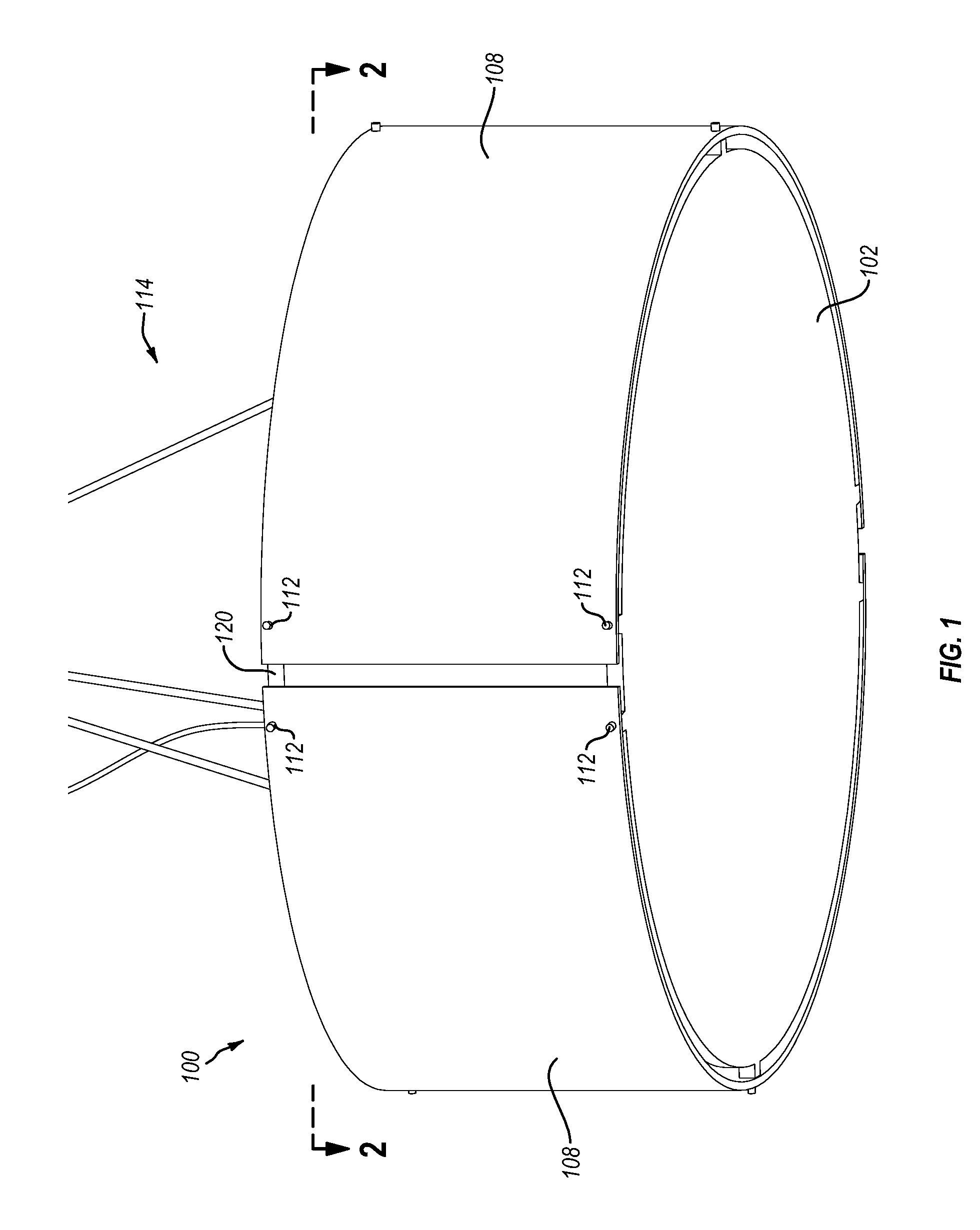
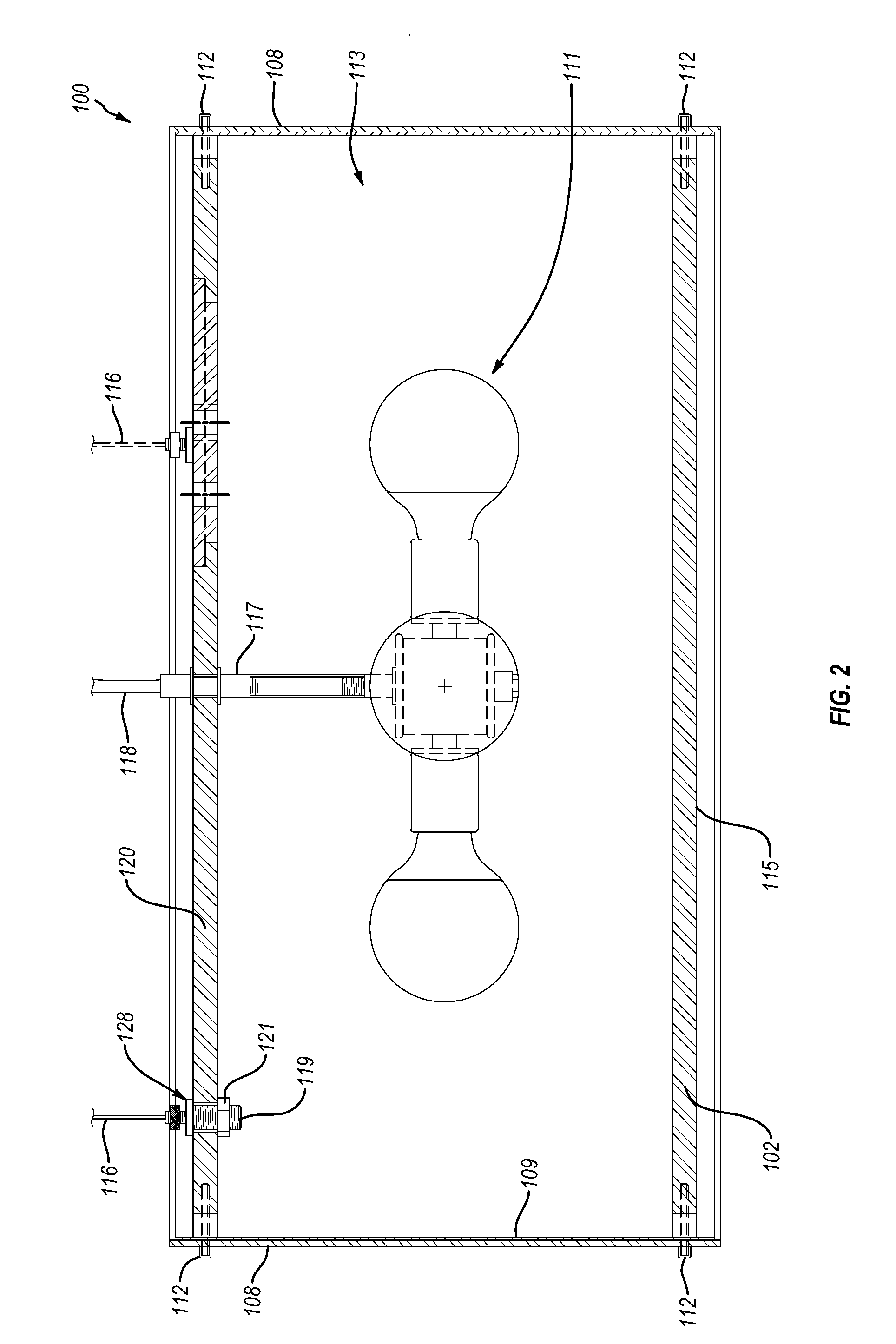
[0026]Implementations of the present invention comprise lighting fixture assemblies that reduce or otherwise minimize the visibility of supporting hardware. In particular, lighting fixture assemblies of the present invention may include one or more external panels that define, in whole or in part, an internal space where light bulbs and / or other electrical components are housed. The internal space of such lighting fixture assemblies may lack hardware extending therethrough. Accordingly, one or more implementations can improve the aesthetic qualities of the lighting fixture assemblies by eliminating the visibility of internal supporting hardware and reducing or eliminating shadows cast by supporting hardware.

[0027]In addition to reducing shadows created by internal hardware, implementations of the present invention may further reduce shadows at the joints of external panels (i.e., side shade panels, top panel, or bottom panel). Specifically, lighting fixture assemblies of the present...


PUM


Abstract

Implementations of the present invention comprise lighting fixture assemblies that minimize the visibility of hardware and shadows. In particular, the lighting fixture assemblies may include no supporting hardware extending through an internal space defined, in whole or in part, by the lighting fixture assembly. In addition, the lighting fixture assemblies may include a gap between a bottom / top panel and a side panel of the lighting fixture assembly. Accordingly, lighting fixture assemblies of one or more implementations of the present invention can reduce or eliminate the visibility of internal supporting hardware and shadows on the exterior surfaces of the lighting fixture assemblies.

Description

CROSS-REFERENCE TO RELATED APPLICATIONS[0001]This application is a 35 U.S.C. §371 U.S. National Stage of PCT Application No. PCT / US2012 / 045754 entitled “Lighting Fixture Assembly,” filed Jul. 6, 2012, which claims priority to and the benefit of U.S. Provisional Patent Application No. 61 / 505,473, filed on Jul. 7, 2011, entitled “Drum Lighting Fixture Assembly.” The entire content of each of the aforementioned patent applications is incorporated herein by reference.BACKGROUND OF THE INVENTION[0002]1. The Field of the Invention[0003]This invention relates generally to lighting fixture assemblies that define, in whole or in part, an internal space that is configured to house light bulbs and / or other electrical circuitry.[0004]2. Background and Relevant Art[0005]Some conventional lighting fixtures, such as drum lighting fixtures, include outer panels that define an internal space that houses light bulbs and / or other electrical circuitry. These lighting fixtures may combine both lighting ...

Claims


Application Information

Patent Timeline
Patent Type & Authority Patents(United States)
IPC IPC(8): F21V1/14F21V21/00
CPCF21V21/00F21V1/14F21V1/12F21V1/146
Inventor SMITH, RYAN GREY
Owner 3FORM
Why Eureka
Try Eureka