Saliency based disparity mapping

a disparity mapping and disparity mapping technology, applied in the field of three-dimensional 3d image processing, can solve the problems of visual discomfort, fatigue or diplopia (double vision, reduced 3d experience of image), and achieve the effects of reducing the 3d experience of image, large shift, and high disparity

Active Publication Date: 2015-05-26
KONINK PHILIPS ELECTRONICS NV
View PDF8 Cites 4 Cited by
  • Summary
  • Abstract
  • Description
  • Claims
  • Application Information

AI Technical Summary

Benefits of technology

[0006]The document above discloses modifying the disparities in image data by applying disparity shift between the left and right view so that the main region of interest has zero disparity. Due to said shift other areas in the image data will get higher disparity than the original data. Such disparities may be beyond the disparity range that the human visual system can comfortably process in a 3D experience, and may lead to visual discomfort, fatigue or diplopia (double vision). The document proposes to apply blurring, e.g. selectively blur a background part of the image, to hide such discomforting areas. Also, due to shifting a high disparity region of interest to zero disparity, a relatively large shift needs to be applied. Hence a problem of the known method is that the 3D experience of the image is reduced.
[0007]It is an object of the invention to provide processing of 3D image data for improving rendering 3D image data having high disparities while avoiding reducing the image quality.

Problems solved by technology

Such disparities may be beyond the disparity range that the human visual system can comfortably process in a 3D experience, and may lead to visual discomfort, fatigue or diplopia (double vision).
Hence a problem of the known method is that the 3D experience of the image is reduced.

Method used


Image

  • Saliency based disparity mapping
  • Saliency based disparity mapping
  • Saliency based disparity mapping

Examples


Embodiment Construction

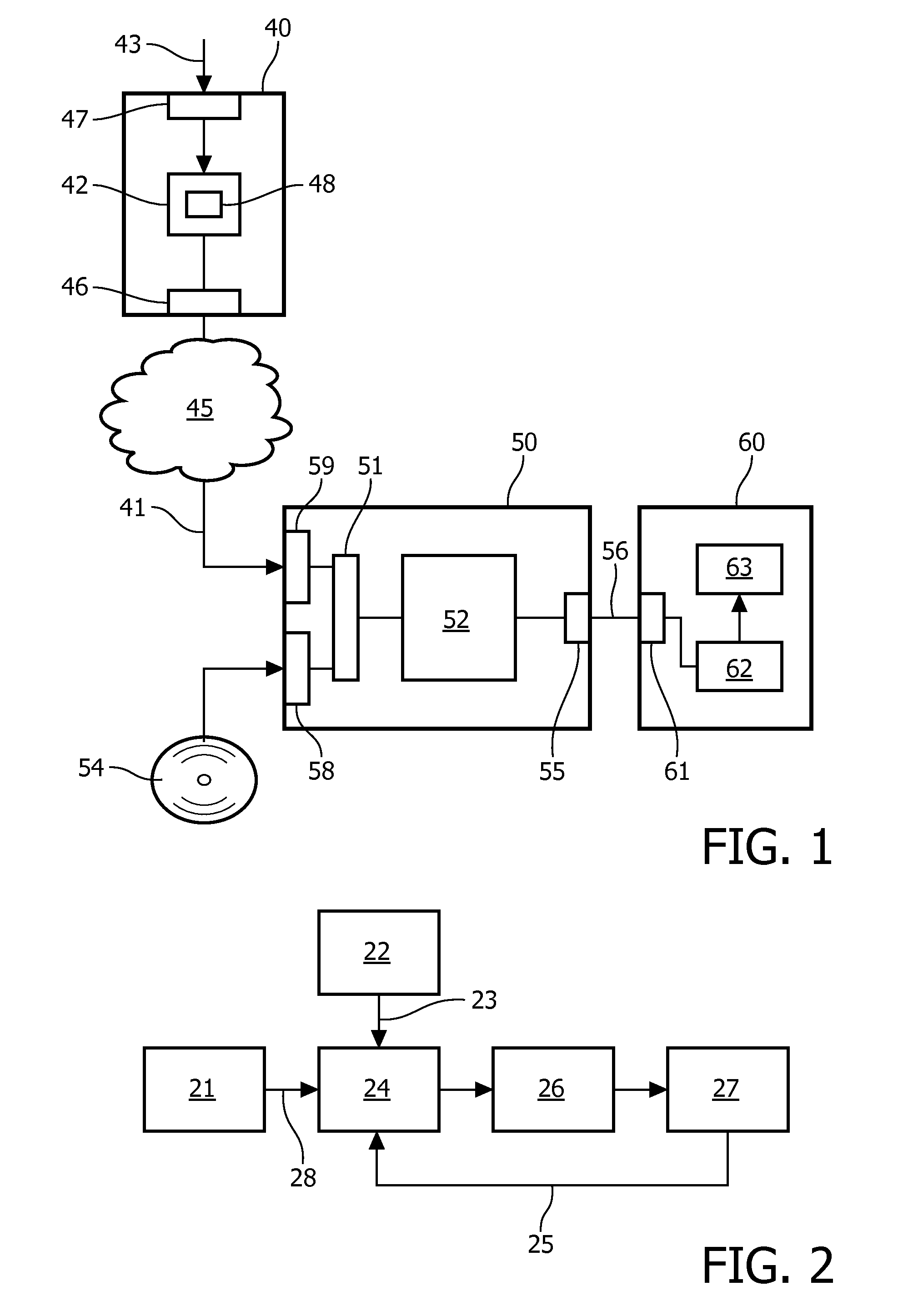
[0034]It is noted that the current invention may be used for any type of 3D image data, either still picture or moving video. The system processes a depth map provided in the 3D image data. The depth map may be either originally present at the input of the system, or may be generated as described below, e.g. from left / right frames in a stereo (L+R) video signal or from 2D video. 3D image data is assumed to be available as electronic, digitally encoded, data. The current invention relates to such image data and manipulates the image data in the digital domain.

[0035]There are many different ways in which 3D video data may be formatted and transferred, called a 3D video format. Some formats are based on using a 2D channel to also carry stereo information. For example the left and right view can be interlaced or can be placed side by side and above and under. Alternatively a 2D image and a depth map may be transferred, and possibly further 3D data like occlusion or transparency data. An...


PUM


Abstract

A three dimensional [3D] image signal is processed for rendering 3D image data (33) on a specific 3D display, e.g. an auto-stereoscopic display. A first depth map (34) and saliency of the 3D image data are determined. A display depth sub-range (35) of a usable depth range (36) of the 3D display is determined and provides a higher 3D image quality for a viewer than the 3D image quality across the usable depth range. A depth mapping function is determined in dependence of the saliency data. The depth mapping function maps the first depth map to a second depth map for generating views for the 3D display. Advantageously the salient range of depth values is mapped towards the display depth sub-range.

Description

CROSS-REFERENCE TO PRIOR APPLICATIONS[0001]This application is the U.S. National Phase application under 35 U.S.C. §371 of International Application PCT / IB2012 / 055829, filed on Oct. 23, 2012, which claims the benefit of U.S. Provisional Patent Application No. 61 / 553,984, filed on Nov. 1, 2011. These applications are hereby incorporated by reference herein.FIELD OF THE INVENTION[0002]The invention relates to a method of processing a three dimensional [3D] image signal for rendering 3D image data on a 3D display based on multiple display views.[0003]The invention further relates to a 3D video device, a 3D image signal and a computer program.[0004]The invention relates to the field of processing 3D image data to improve rendering on a 3D display device. In particular a depth map, either available or generated, is processed for improving the 3D experience on a particular 3D display. Image data here includes video data, and is usually processed in two spatial dimensions, whereas time in ...

Claims


Application Information

Patent Timeline
Patent Type & Authority Patents(United States)
IPC IPC(8): G06T15/00G06T15/04H04N13/00
CPCG06T15/04H04N13/0022H04N13/128
Inventor BRULS, WILHELMUS HENDRIKUS ALFONSUSKOON, BARTVANDEWALLE, PATRICK LUC ELS
Owner KONINK PHILIPS ELECTRONICS NV
Why Eureka
Try Eureka